Water removing and weight reducing device for kitchen waste

A technology of food waste and shell, which is applied in the field of dehydration and weight reduction devices for food waste, can solve the problems of high energy consumption and complex structure, and achieve the effects of sufficient drying and weight reduction, high treatment efficiency and good treatment effect

Inactive Publication Date: 2018-01-19
ZIBO YUMING VENTILATION EQUIP CO LTD
View PDF10 Cites 2 Cited by
  • Summary
  • Abstract
  • Description
  • Claims
  • Application Information

AI Technical Summary

Problems solved by technology

[0003] The purpose of the present invention is to aim at the technical defects of the prior art, and provide a dehydration and weight reduction device for kitchen waste, so as to solve the technical problems of high energy consumption and complex structure of related devices in the prior art

Method used


Image

  • Water removing and weight reducing device for kitchen waste
  • Water removing and weight reducing device for kitchen waste

Examples


Embodiment 1

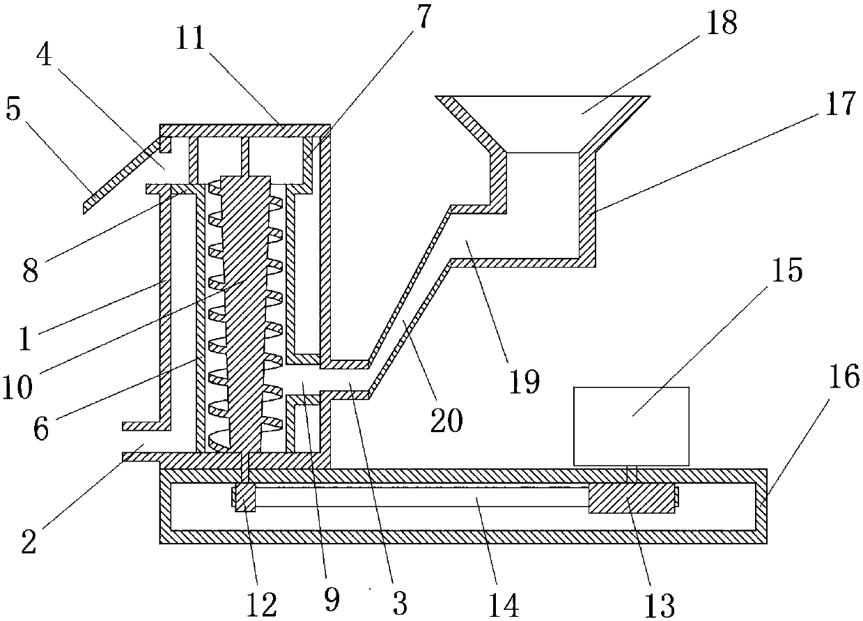
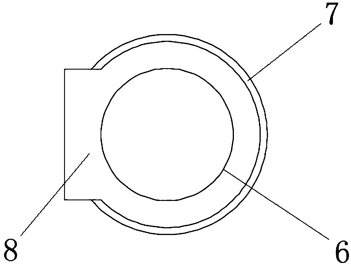
[0027] A dehydration and weight reduction device for kitchen waste, comprising a housing 1, a liquid discharge port 2, a feed port 3, a discharge port 4, a baffle plate 5, an inner sleeve 6, an enclosure 7, a table top 8, and a Feeding port 9, variable diameter screw 10, shaft seat 11, driven timing gear 12, driving timing gear 13, timing belt 14, motor 15, abutment 16, feeding bin 17, funnel 18, feeding port 19, feeding Tube 20, wherein the inner sleeve 6 has a number of through holes on the side wall, the housing 1 and the motor 15 are fixedly connected to the base 16, the lower part of the side wall of the housing 1 has a liquid discharge port 2 and a feed port 3, the shell The upper part of the side wall of the body 1 has a discharge port 4, one end of the baffle plate 5 is fixedly connected to the upper end of the side wall of the housing 1, and the other end is inclined downward, the baffle plate 5 is located at the discharge port 4, and the inner sleeve 6 is socketed in...

Embodiment 2

[0033] A dehydration and weight reduction device for kitchen waste, comprising a housing 1, a liquid discharge port 2, a feed port 3, a discharge port 4, a baffle plate 5, an inner sleeve 6, an enclosure 7, a table top 8, and a Feeding port 9, variable diameter screw 10, shaft seat 11, driven timing gear 12, driving timing gear 13, timing belt 14, motor 15, abutment 16, feeding bin 17, funnel 18, feeding port 19, feeding Pipe 20, wherein, there are several through holes on the side wall of the inner sleeve 6, the housing 1 and the motor 15 are fixedly connected to the base 16, the lower part of the side wall of the housing 1 has a liquid discharge port 2 and a feed port 3, the shell The upper part of the side wall of the body 1 has a discharge port 4, one end of the baffle plate 5 is fixedly connected to the upper end of the side wall of the housing 1, and the other end is inclined downward, the baffle plate 5 is located at the discharge port 4, and the inner sleeve 6 is socke...

Embodiment 3

[0043] A dehydration and weight reduction device for kitchen waste, comprising a housing 1, a liquid discharge port 2, a feed port 3, a discharge port 4, a baffle plate 5, an inner sleeve 6, an enclosure 7, a table top 8, and a Feeding port 9, variable diameter screw 10, shaft seat 11, driven timing gear 12, driving timing gear 13, timing belt 14, motor 15, abutment 16, feeding bin 17, funnel 18, feeding port 19, feeding Tube 20, wherein the inner sleeve 6 has a number of through holes on the side wall, the housing 1 and the motor 15 are fixedly connected to the base 16, the lower part of the side wall of the housing 1 has a liquid discharge port 2 and a feed port 3, the shell The upper part of the side wall of the body 1 has a discharge port 4, one end of the baffle plate 5 is fixedly connected to the upper end of the side wall of the housing 1, and the other end is inclined downward, the baffle plate 5 is located at the discharge port 4, and the inner sleeve 6 is socketed in...


PUM


Abstract

The invention provides a water removing and weight reducing device for kitchen waste. According to the technical scheme, a shell, an inner sleeve and a variable diameter spiral are sequentially embedded from exterior to interior. The variable diameter spiral is driven by a motor through a timing gear to upwards convey the kitchen waste which enters from a feed port and a material conveying opening, and due to the fact that the variable diameter spiral can generate relatively high extrusion force to the material in the conveying process, the water can be extruded out and flow out through through holes in the inner sleeve. The extruded water is accumulated between the inner sleeve and the shell and then is drained out of a liquid draining opening, and the dry material conveyed to the upper end is discharged through a discharge port under the rotation action. According to the water removing and weight reducing device for the kitchen waste, the material conveying and extrusion water removing effects are combined, sufficient drying and weight reducing can be achieved, the operation process is uninterrupted and can be continuously completed, and extremely high treatment efficiency is achieved.

Description

technical field [0001] The invention relates to the technical field of kitchen waste treatment, in particular to a dehydration and weight reduction device for kitchen waste. Background technique [0002] Kitchen waste, commonly known as swill, also known as swill and swill, is the domestic waste formed by residents in the process of daily consumption. It is easy to rot and deteriorate, emits foul smell, and spreads bacteria and viruses. The main components of food waste include rice and flour food residues, vegetables, animal and vegetable oils, meat and bones, etc. From the chemical composition, there are starch, cellulose, protein, lipids and inorganic salts. Due to the complex composition and high organic matter content, food waste treatment is an important and relatively independent technical link in environmental governance technology. In the process of food waste treatment, whether it is transported in the early stage or biodegraded in the later stage, it needs to be ...

Claims


Application Information

Patent Timeline
Patent Type & Authority Applications(China)
IPC IPC(8): B30B9/12B30B9/14
Inventor 李国
Owner ZIBO YUMING VENTILATION EQUIP CO LTD
Why Eureka
Try Eureka