Hydraulic system of crane

A hydraulic system and crane technology, applied in cranes, fluid pressure actuation system components, mechanical equipment, etc., can solve the problems of increasing the leakage of the hydraulic system, reducing the speed of lifting operations, and failure of the sealing ring, so as to increase the leakage amount and avoid serious effects of resource consumption

Pending Publication Date: 2018-01-19
HUADIAN ZHENGZHOU MECHANICAL DESIGN INST
View PDF6 Cites 2 Cited by
  • Summary
  • Abstract
  • Description
  • Claims
  • Application Information

AI Technical Summary

Problems solved by technology

[0004] The purpose of the present invention is to provide a new hydraulic system of a crane to solve the problem that the temperature of the hydraulic oil rises too high during the long-term lifting operation of the crane in the above background technology, which makes the sealing ring invalid and increases the leakage of the hydraulic system. Reduce the speed of the lifting operation, which affects the normal operation of the crane. In addition, when the crane is performing lifting operations, the hydraulic cylinder moves the piston, and the return oil directly enters the hydraulic oil tank through the pipeline, which will easily cause oil pollution to follow the hydraulic oil into the hydraulic oil tank, causing hydraulic pressure. The oil is impure, causing blockage of the hydraulic oil pipe and affecting the normal operation of the hydraulic system

Method used


Image

  • Hydraulic system of crane
  • Hydraulic system of crane
  • Hydraulic system of crane

Examples


Embodiment Construction

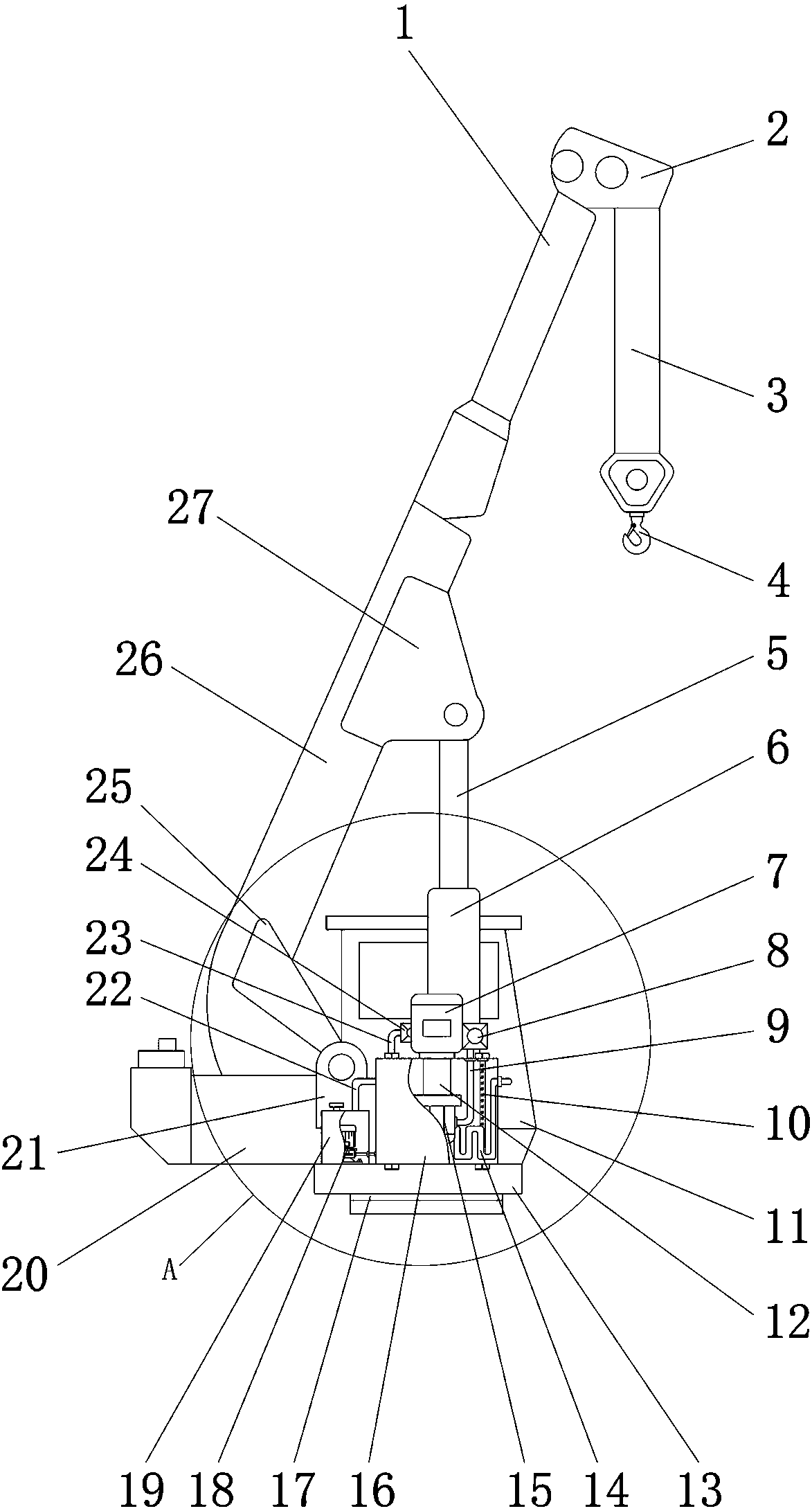
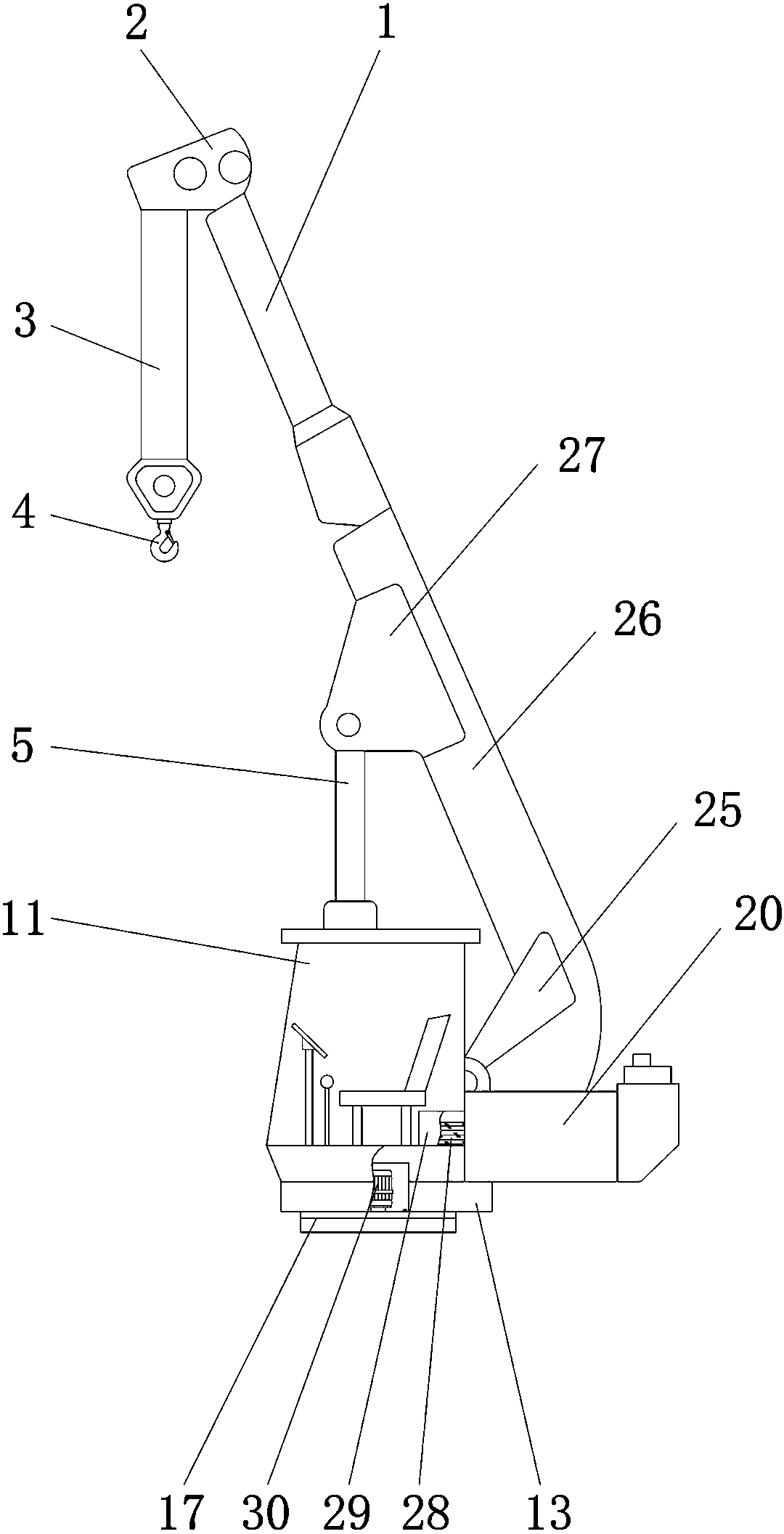
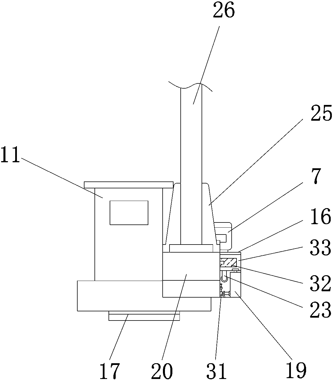
[0023] The present invention will be described in further detail below in conjunction with the accompanying drawings and specific embodiments.

[0024] The present invention provides a hydraulic system of a crane, comprising a base 13, a fuselage 20 is arranged on the top of the base 13, a turning mechanism 17 is arranged at the middle position of the bottom of the base 13, and a hydraulic motor 30 is arranged at an inner middle position of the turning mechanism 17; the fuselage 20 The top of the main arm 26 is fixed, and the top of the main arm 26 is equipped with a suspension hook 4 . The hydraulic motor 30 drives the slewing mechanism 17 to rotate, and then drives the fuselage 20 to rotate, so that the main arm 26 can be hoisted in different directions.

[0025] The top of the base 13 is also provided with a control room 11, through which the hoisting is operated, the control room 11 and the fuselage 20 are located on the same horizontal line, and the control room 11 is loc...


PUM


Abstract

The invention provides a hydraulic system of a crane. The hydraulic system of the crane comprises a crane body, wherein a main arm is fixed at the upper part of the crane body; a hydraulic oil tank isfixed on the side of the crane body; a motor and a one-way throttle valve are mounted at the top of the hydraulic oil tank; a gear pump is arranged inside the hydraulic oil tank; an S-shaped coolingpipe is arranged under the gear pump; the gear pump is connected with the motor through a coupler; the gear pump is connected with the one-way throttle valve through a hydraulic oil pipe; an oil storage tank is arranged on the hydraulic oil tank; a filtering net is arranged between the oil storage tank and the hydraulic oil tank; the oil storage tank is connected with an oil returning pipe; a balancing valve is mounted in the oil returning pipe; a cooling water tank is also fixed on the side of the crane body; a water pump is arranged in the cooling water tank; a booster pump communicated withthe cooling water tank is arranged on the side of the cooling water tank; a water pump is communicated with a water inlet of the S-shaped cooling pipe through a pipeline. According to the hydraulic system of the crane, the S-shaped cooling pipe is used for cooling the hydraulic oil, so that the problem that the temperature of the hydraulic oil is increased to an excessively high temperature whenthe crane carries out the hoisting operation for a long time is solved.

Description

technical field [0001] The invention belongs to the technical field of hydraulic systems, and in particular relates to a hydraulic system of a crane. Background technique [0002] Truck crane is a kind of widely used construction machinery. This kind of machinery can travel at a relatively fast speed. Transportation, urban construction, fire protection, large material yards, infrastructure, first aid and other fields have been widely used; when the crane is working, it relies on four hydraulic couplings to lift the entire car, and unfolds various parts of the crane for lifting operations , due to the relatively simple actions to be completed by the actuators of the hydraulic system and the low position accuracy requirements, the reliability and safety of the hydraulic system are the most important for the hydraulic system of the hoisting machinery. [0003] However, the hydraulic system currently on the market still has certain defects during the lifting operation of the cr...

Claims


Application Information

Patent Timeline
Patent Type & Authority Applications(China)
IPC IPC(8): F15B21/04B66C13/20B66C23/86
Inventor 李俊林喜振许守亮李旻辰李箴上官高峰
Owner HUADIAN ZHENGZHOU MECHANICAL DESIGN INST
Why Eureka
Try Eureka