Graphite radiator and integral forming method thereof

A technology of integral molding and radiator, which is applied in the direction of indirect heat exchangers, heat exchange equipment, and other household appliances. It can solve the problems of small convective heat transfer coefficient, difficulty in integral molding, and poor heat dissipation effect, and achieve convective heat transfer. High coefficient, low production cost, good heat dissipation effect

Active Publication Date: 2018-01-19
CHINA THREE GORGES UNIV
View PDF6 Cites 5 Cited by
  • Summary
  • Abstract
  • Description
  • Claims
  • Application Information

AI Technical Summary

Problems solved by technology

[0005] The present invention provides a graphite heat sink and its integral molding method, in order to solve the problems of relatively simple structure, small h

Method used


Image

  • Graphite radiator and integral forming method thereof
  • Graphite radiator and integral forming method thereof

Examples


Embodiment 1

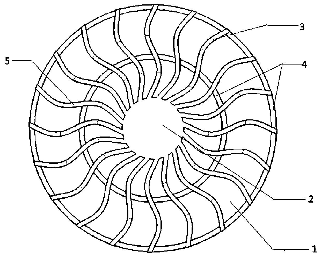
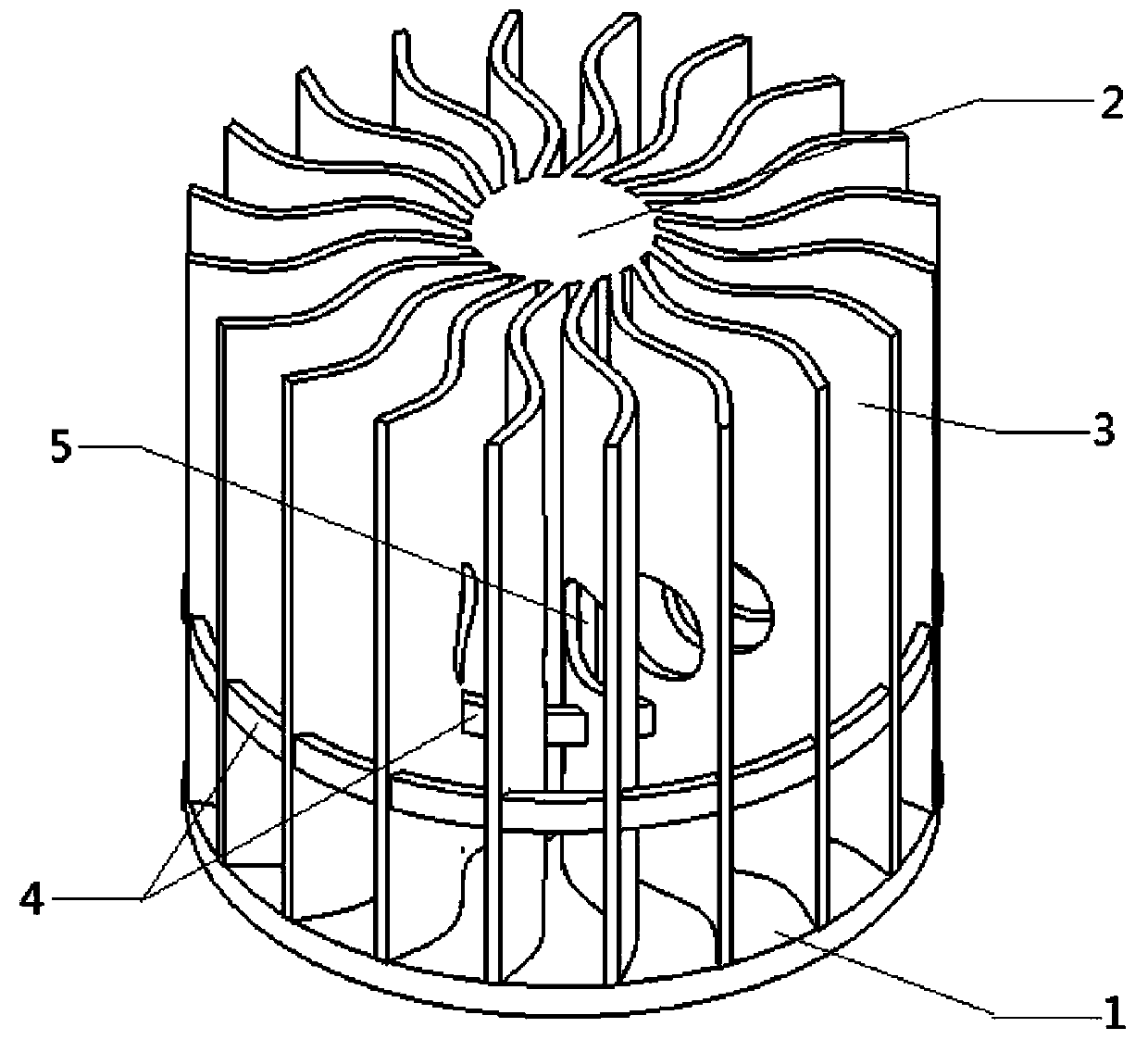
[0020] As shown in the figure, a graphite radiator provided in this embodiment includes a heat dissipation substrate 1, a thermal column 2, 20 heat dissipation fins 3 and 2 connecting ribs 4; the thermal column 2 is arranged at the center 1 of the heat dissipation substrate, 20 cooling fins 3 are radially distributed with the heat column 2 as the center. In order to improve the convective heat transfer coefficient, the above-mentioned cooling fins 3 are provided with small holes 5. In order to increase the cooling area, the cooling fins 3 are designed to be curved. At different radii in the circumferential direction of the graphite radiator, connecting ribs 4 are designed to connect the cooling fins 3 together to improve the overall rigidity. The specific dimensions of this embodiment are as follows: substrate diameter 40mm, thickness 2mm; heat column diameter 10mm, height 35mm; 0.8mm. Compared with the general straight fin structure, the heat dissipation area of ​​this struc...

Embodiment 2

[0028] As shown in the figure, the present invention provides a graphite heat sink, comprising a heat dissipation substrate 1, a thermal column 2, 15 heat dissipation fins 3 and 2 connecting ribs 4; The column 2 is the center and 15 heat dissipation fins 3 are distributed radially. In order to improve the convective heat transfer coefficient, the above heat dissipation fins 3 are provided with small holes 5. In order to increase the heat dissipation area, the heat dissipation fins 3 are designed as a curved surface to dissipate heat along the graphite. At different radii in the circumferential direction of the device, connecting ribs 4 are designed to connect the cooling fins 3 together to improve the overall rigidity. The specific dimensions of this embodiment are as follows: substrate diameter 40mm, thickness 2mm; heat column diameter 10mm, height 35mm; 0.8mm. Compared with the general straight fin structure, this structure increases the heat dissipation area by 6.4%.

[0...


PUM

PropertyMeasurementUnit
Diameteraaaaaaaaaa
Thicknessaaaaaaaaaa
Thicknessaaaaaaaaaa

Abstract

The invention relates to a graphite radiator and an integral forming method thereof. The graphite radiator is composed of a radiating base plate, a thermal column, radiating fins and connecting rib pieces, wherein the thermal column is placed in the center of the radiating base plate; the radiating fins are radially distributed by taking the thermal column as the center; small holes are formed inthe radiating fins to increase the convective heat transfer coefficient; the radiating fins are designed to be hook face to increase the radiating area; and the connecting rib pieces are designed at different radius parts in the peripheral direction of the graphite radiator. The graphite radiator is integrally formed and comprises the technological links of mixed powder preparation, integral 3D printing forming, prefab preparation, carbonization and buried carbon high-temperature sintering. The integral forming method is simple in technology, practical and low in production cost and can manufacture a complicated graphite radiator; and the graphite radiator has the characteristics of being large in superficial area and high in convective heat transfer coefficient, strength, rigidity and radiating effect and has broad application prospect in the radiating field.

Description

technical field [0001] The invention belongs to the technical field of heat dissipation of electronic devices, and in particular relates to a graphite radiator and an integral forming method thereof. Background technique [0002] Usually, electronic devices will generate a lot of heat when they work. If the heat dissipation is not good, it will generate high temperature, which will affect the normal working state of electronic devices, resulting in unstable system performance and even damage. Relevant data show that for electronic equipment, 50% of the current failure problems are caused by overheating of electronic devices. In addition, with the continuous innovation of science and technology, the integration density of large-scale integrated circuits continues to increase, the running speed of microprocessors is getting faster and faster, and more and more functions are integrated in a single chip. Will be more. This means that electronic chips will get hotter and hotter...

Claims


Application Information

Patent Timeline
IPC IPC(8): F28D21/00F28F21/02C04B35/532C04B35/634B33Y70/00C04B35/622C04B41/87C04B38/06
Inventor 吴海华李腾飞肖林楠鄢俊能彭建辉
Owner CHINA THREE GORGES UNIV
Why Eureka
Try Eureka