

Novel integrated information recorder for fishing vessel
An information integration and recorder technology, applied in the direction of instruments, registration/indication, time register, etc., can solve the problem that marine fishery resources are far from being realized, and achieve convenient embedded installation or hanging installation, convenient operation, and utilization rate. high effect
- Summary
- Abstract
- Description
- Claims
- Application Information
AI Technical Summary
Problems solved by technology
Method used
Image

Examples
Embodiment 1
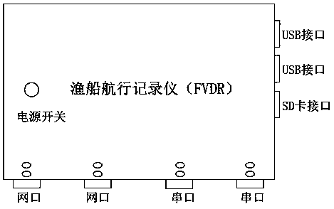
[0030] Such as Figure 1~2 As shown, it is an implementation mode of the new fishing boat information comprehensive recorder, and the main body layout of the fishing boat sailing recorder is as follows figure 1 , the upper surface of the recorder has a power switch button to control the working status of the recorder. There are two USB ports and SD ports on the right side of the recorder. , the SD interface is used to connect the SD card. There are two network ports and two serial ports on the lower side of the recorder to meet the equipment on the fishing boat that transmits data through the network port interface or serial interface. Multi-device matching.
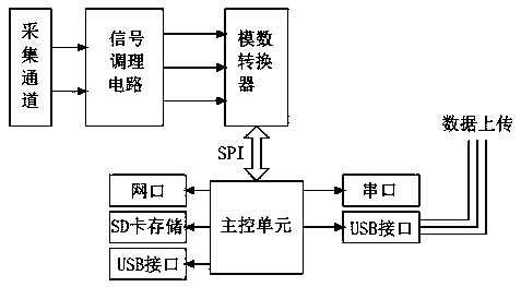
[0031] The circuit diagram of the recorder is as follows: figure 2 As shown, the circuit system is planned to use the microprocessor STM32F103 series chip STM32F103ZET6 based on the ARM Cortex™-M3 core as the main control unit, which is responsible for the communication data coordination, clock control, display contro...
Embodiment 2
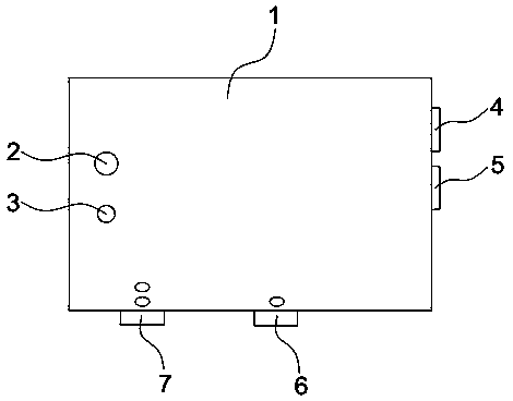
[0035] Such as Figure 3~12 As shown, a novel fishing boat information comprehensive recorder is an optimization scheme of embodiment 1. The recorder includes a box body 1, a power switch 2 and an indicator light 3 are installed on the upper surface of the box body 1, and a USB interface is installed on the side of the box body 1. 4, SD card interface 5, serial interface 6 and network interface 7, circuit main board 27 and power supply module are installed inside casing 1, and circuit main board 27 is provided with data acquisition module 19, and data acquisition module 19 is network port module 23, SD card module 24, USB module 25 and serial port module 26, the recorder of the present invention is provided with multi-channel data acquisition channel, can realize the connection to the fishing boat equipment of different data interface types, has improved the convenience of data synchronization greatly, box body 1 High integration, convenient operation, and good coordination wi...
Embodiment 3
[0046] Such as Figure 3~12 As shown, a new type of fishing boat information comprehensive recorder, its working principle is: the recorder is installed on the hull, and the existing equipment on the fishing boat is connected to the corresponding channel interface of the recorder through a USB cable, a network cable or a serial line , the power supply input of the recorder is 220V / 50H as the power supply, the power switch 2 of the recorder is turned on to make the recorder work, the data acquisition module 19 regularly collects data, and the collected signal is amplified and filtered by the signal conditioning circuit 20 and passed to the analog-to-digital converter 21, The analog-to-digital converter 21 converts the data analog signal into a data digital signal and transmits it to the main control unit 22STM32F103ZET6. The main control unit 22 writes the data into the SD card module 24 for storage through software. When the data needs to be extracted and analyzed, the PC termi...
PUM
| Property | Measurement | Unit |
|---|---|---|
| Density | aaaaa | aaaaa |
| Thermal conductivity | aaaaa | aaaaa |
| Density | aaaaa | aaaaa |
Abstract
Description
Claims
Application Information