Multiband broadband dipole antenna with coupling stubs

A broadband dipole and dipole technology, applied in the direction of resonant antenna, antenna grounding switch structure connection, mid-position feed between antenna terminals, etc., to achieve good matching, increase working bandwidth, and increase working frequency band

Pending Publication Date: 2018-01-19
FOSHAN SHUNDE SUN YAT SEN UNIV RES INST +2
View PDF10 Cites 12 Cited by
  • Summary
  • Abstract
  • Description
  • Claims
  • Application Information

AI Technical Summary

Problems solved by technology

[0004] The traditional broadband technology of slotting lines on the antenna achieves the introduction of multiple resonant frequencies, and it is also possible to introduce unwanted frequencies

Method used


Image

  • Multiband broadband dipole antenna with coupling stubs
  • Multiband broadband dipole antenna with coupling stubs
  • Multiband broadband dipole antenna with coupling stubs

Examples


Embodiment 1

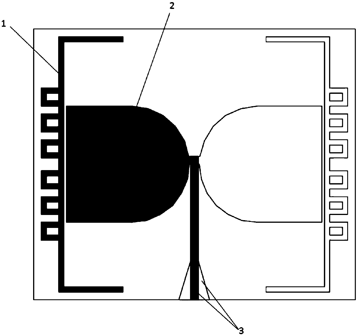
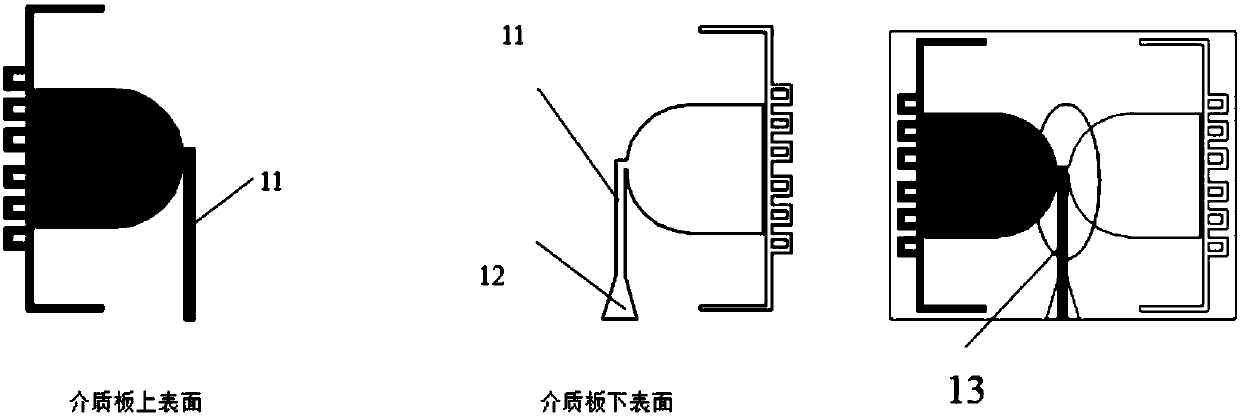
[0028] like figure 1 As shown, the structure diagram of a dipole antenna combined with a semicircle and a rectangle with a coupling branch, the two dipole arms of the dipole antenna are printed on the upper and lower sides of the dielectric board, and one dipole arm is rotated 180 degrees The rear is symmetrical with another dipole arm based on a dielectric plate. The first half of the dipole arm adopts a semicircular structure, and the second half is connected to a rectangular structure. The coupling branch adopts a rectangular strip, and a small rectangle is added to the coupling branch to increase the inductance of the antenna to offset the capacitance caused by coupling. The dipole arm plays the role of widening the frequency band, and the coupling branch introduces a new working mode and increases the working frequency band. The microstrip balun feeders are respectively connected to the dipole arms at the center of the dielectric plate, and can play the role of impedance...

Embodiment 2

[0034] like Figure 4 As shown, the dipole antenna structure with the snowflake fractal and rectangular combination of coupling branches, the structure of the antenna is similar to the antenna of the above-mentioned embodiment 1, for the good characteristics and miniaturization of the antenna, the semicircle and the The fractal form is improved for the long rectangular coupling stub, the semicircle is replaced by the third-order Koch snowflake fractal, and the rectangular coupling stub is replaced by the second-order Koch fractal. The size of the antenna is reduced as much as possible while keeping the general performance unchanged. In order to make better coupling between the dipole arm and the coupling branch, rectangular strips are still used in the strong coupling part to increase the contact area between the coupling branch and the dipole arm, so as to achieve the best coupling effect. The Koch snowflake fractal maintains the broadband characteristics of the antenna, and ...


PUM


Abstract

The invention discloses a multiband broadband dipole antenna with coupling stubs. The multiband broadband dipole antenna comprises a dielectric board, two dipole arms, two coupling stubs and a microstrip balun feeder. The two dipole arms and the two couplings stubs are printed on both sides of the dielectric board, respectively. The dipole arm and the coupling stub on the same plane are rotated by180 degrees and then are symmetrical with the dipole arm and the coupling stub on the other plane based on the dielectric board. The dipole arms play the role of widening the frequency band, and thecoupling stubs introduce a new mode of work to increase the working frequency band of the antenna. Semicircular parts in the dipole arms and the coupling stubs are both in a fractal form, and the antenna area is reduced without changing the performance. In the impedance matching, the invention introduces a small rectangle to increase the inductance of the antenna to counteract the capacitance caused by the coupling, so that the antenna can achieve a good match without the need of a complicated peripheral matching circuit.

Description

technical field [0001] The invention relates to the field of multi-frequency broadband dipole antennas, and more specifically, relates to a multi-frequency broadband dipole antenna with coupling stubs. Background technique [0002] With the advancement of mobile communication into the 5G era, dipole antennas are widely used in the fields of mobile communication devices and microwave energy collection and transmission due to their simple structure, low manufacturing cost and good performance. A traditional dipole antenna consists of two conductors fed at a central location with a total length of about half a wavelength and is the basic unit of most antennas. The dipole antenna has a certain improvement in gain pattern performance compared with the monopole antenna, and can obtain satisfactory pattern characteristics, and the dipole antenna has good radiation characteristics, wavelength shortening effect and resonance characteristics. By controlling the relationship between t...

Claims


Application Information

Patent Timeline
Patent Type & Authority Applications(China)
IPC IPC(8): H01Q1/38H01Q1/50H01Q9/28
Inventor 谭洪舟陈智聪曾淼旺安德烈·安德烈尼克路崇
Owner FOSHAN SHUNDE SUN YAT SEN UNIV RES INST
Why Eureka
Try Eureka