
Parameter design method and control method and system of lc coupling type SVG under unbalanced power grid

A coupling type, power grid technology, applied in flexible AC transmission systems, multiphase network asymmetry reduction, multiphase network elimination/reduction of asymmetry, etc., can solve the problem of large capacitor voltage, high apparent power, and increase the cost of compensation devices and switching losses

Active Publication Date: 2020-04-07
STATE GRID HUNAN ELECTRIC POWER +2
View PDF5 Cites 0 Cited by
  • Summary
  • Abstract
  • Description
  • Claims
  • Application Information

AI Technical Summary

Problems solved by technology

[0007] 1. The traditional SVG can comprehensively solve power quality problems such as reactive power and three-phase imbalance in the grid. However, when this topology compensates capacitive reactive power, the voltage output by the VSC inverter is greater than the grid voltage, resulting in DC The side capacitor voltage is relatively large, generally about twice the grid voltage, so that the apparent power output by the VSC is relatively high, correspondingly increasing the cost of the compensation device and switching loss, affecting its popularization and application
[0008] 2. LC-coupled SVG can effectively reduce the DC side capacitor voltage, but most of them are currently used in balanced systems and only compensate reactive power. At this time, the design of series LC parameters on the grid-connected branch is generally based on the required reactive capacity The LC parameter design method is not suitable for the comprehensive compensation of reactive power and negative sequence in unbalanced systems, and cannot minimize the DC side voltage
[0009] 3. The control strategy currently proposed for the LC-coupled SVG system only includes the balance control of reactive power compensation and DC voltage stability, and cannot compensate the negative sequence current in the unbalanced system, and lacks a corresponding unbalanced control Strategy

Method used


Image

  • Parameter design method and control method and system of lc coupling type SVG under unbalanced power grid
  • Parameter design method and control method and system of lc coupling type SVG under unbalanced power grid
  • Parameter design method and control method and system of lc coupling type SVG under unbalanced power grid

Examples


Embodiment Construction

[0046] The present invention will be further described below in conjunction with the accompanying drawings and embodiments.

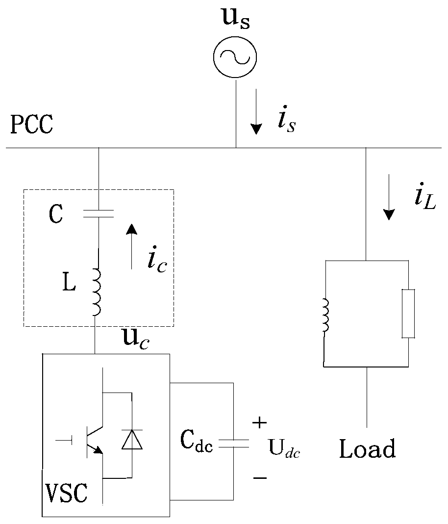
[0047] The main circuit system structure of LC coupled SVG (LC-SVG for short) is as follows: figure 1 As shown, compared with the traditional SVG, a capacitor C connected in series with the filter inductor L is added on the grid-connected branch. figure 1 Among them, the voltage source converter (VSC) adopts a typical two-level structure, u s is the power supply voltage of distribution network; u c is the fundamental wave component of the VSC inverter output voltage, and the load is resistive and inductive; i s i L and i c Respectively, grid side output current, load current and VSC output compensation current; U dc is the DC side capacitor C dc Voltage.

[0048] When the LC-SVG compensation device is used to realize reactive power and unbalanced load compensation, the compensation current that VSC needs to output includes positive sequence react...


PUM


Abstract

The invention discloses a parameter design method of an LC coupling type SVG under an unbalanced power grid and its control method and system. The parameter design method makes the required voltage on the DC side the minimum, and compensates reactive power and negative sequence current in the unbalanced power grid. ; When the LC-coupled SVG circuit determined by this method is used to compensate capacitive reactive power, the VSC inverter output voltage is smaller than the grid voltage, thereby greatly reducing the DC side capacitor voltage, reducing power and switching losses, and reducing The cost is reduced; the control method is based on an unbalanced control strategy combining the compensation reference current detection of the improved generalized integrator (SOGI) and the quasi-proportional resonance (QPR) control. Tracking control, the whole control link is very simple, and can eliminate the delay and error in the control process.

Description

technical field [0001] The invention belongs to the field of power grid control, and in particular relates to a parameter design method of an LC coupling type SVG under an unbalanced power grid, a control method and a system thereof. Background technique [0002] At present, the distribution network mainly faces power quality problems such as low system power factor and three-phase imbalance. The low power factor of the system is caused by excessive reactive current, which will increase equipment and line losses, reduce the utilization rate of power transmission and transformation equipment, and thus increase operating costs; while three-phase imbalance will generate negative sequence current, negative sequence The current will cause additional heat loss inside the generator and transformer, and also cause relay protection and automatic device malfunction. The above problems have increasingly seriously affected the safe and stable operation of the distribution network and e...

Claims


Application Information

Patent Timeline
Patent Type & Authority Patents(China)
IPC IPC(8): H02J3/18H02J3/26
CPCY02E40/10Y02E40/50
Inventor 周冠东陈跃辉罗培严文交黄强
Owner STATE GRID HUNAN ELECTRIC POWER
Learn More