Livestock feed crushing device with iron removal function

A pulverizing device and livestock technology, applied in the directions of feed, drying gas arrangement, dispersing particle filtration, etc., can solve the problems of inconvenient discharge, no iron removal function, poor pulverization effect, etc., and achieve convenient iron removal and good pulverization treatment effect. , the effect of improving quality

Inactive Publication Date: 2018-01-26
沈美珍
View PDF0 Cites 7 Cited by
  • Summary
  • Abstract
  • Description
  • Claims
  • Application Information

AI Technical Summary

Problems solved by technology

[0002] Feed is indispensable for agriculture. Feed often requires the use of a feed grinder. The feed grinder is mainly used to crush various feeds and various roughages. The purpose of feed grinding is to increase the surface area of ​​the feed and adjust the particle size. Increasing the surface area improves the palatability. And it is easy to contact with the digestive juice in the digestion side, which is beneficial to improve the digestibility and better absorb the nutritional components of the feed; on the one hand, the adjustment of the particle size reduces the energy consumed by the chewing of livestock and poultry, on the other hand, it is harmful to the transportation, storage, mixing and preparation. Granulation is more convenient, with better efficiency and quality; the existing device for processing feed has poor crushing effect and is not easy to discharge; at the same time, it does not have the function of iron removal; therefore, it needs to be improved

Method used

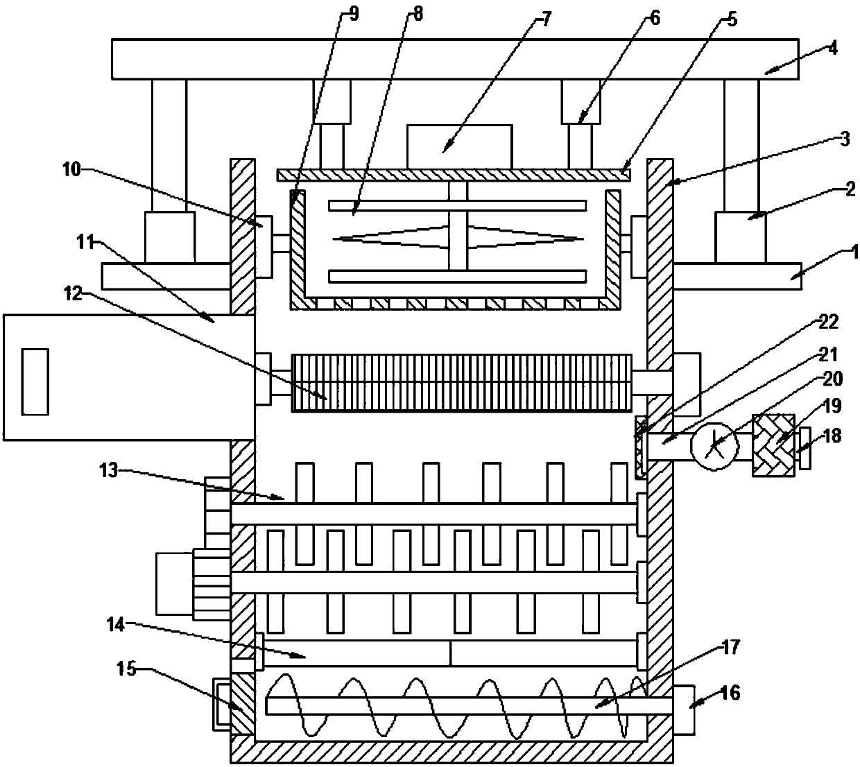

Image

  • Livestock feed crushing device with iron removal function
  • Livestock feed crushing device with iron removal function
  • Livestock feed crushing device with iron removal function

Examples


Embodiment Construction

[0016] The technical solution of this patent will be further described in detail below in conjunction with specific embodiments.

[0017] Embodiments of the present patent are described in detail below, examples of which are shown in the drawings, wherein the same or similar reference numerals designate the same or similar elements or elements having the same or similar functions throughout. The embodiments described below by referring to the figures are exemplary and are only used for explaining the patent, and should not be construed as limiting the patent.

[0018] In the description of this patent, it is to be understood that the terms "center", "upper", "lower", "front", "rear", "left", "right", "vertical", "horizontal", The orientation or positional relationship indicated by "top", "bottom", "inner", "outer", etc. is based on the orientation or positional relationship shown in the drawings, and is only for the convenience of describing this patent and simplifying the des...


PUM


Abstract

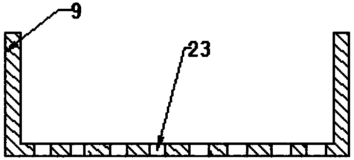
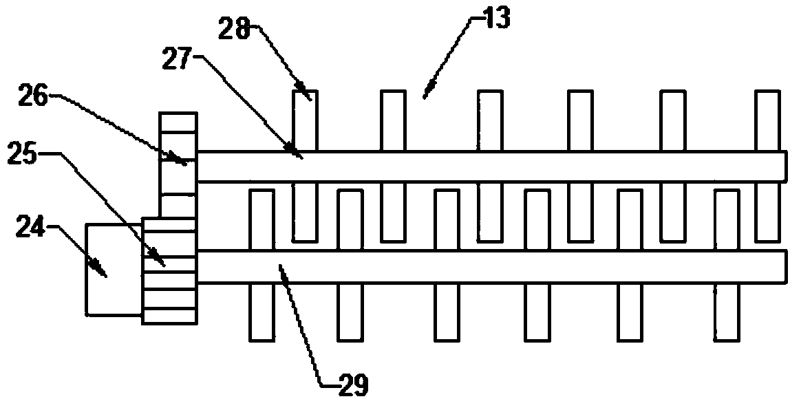
The invention provides a livestock feed crushing device with an iron removal function, and belongs to the technical field of livestock feed processing. A cover plate is welded to and fixedly arrangedat the lower ends of telescopic rods. An electromotor is fixedly arranged on the upper portion of the cover plate. A first crushing device is fixedly arranged on the lower portion of the electromotor.A screening vessel is arranged on the upper side of an inner cavity of a crushing box through a supporting frame. An iron taking bin door is arranged on the outer side of an iron removal device. A second crushing device is arranged on the lower side of the iron removal device. An electric telescopic plate is arranged on the lower side of the inner cavity of the crushing box. A spiral crushing device is arranged at the left end of a first motor. According to the livestock feed crushing device, through holes are formed in the bottom of an inner cavity of the screening vessel, and the function of screening feed with the dimension diameters meeting the standard is achieved; a moisture exhaust fan is arranged on the right side of the crushing box through an exhaust pipe, and the function of removing moisture in the feed is achieved; and the device has the beneficial effects of being simple in structure, high in practicality and good in crushing treatment effect.

Description

technical field [0001] The invention relates to a livestock feed processing facility, in particular to a livestock feed crushing device with the function of removing iron. Background technique [0002] Feed is indispensable in agriculture. Feed often requires the use of feed mills. Feed grinders are mainly used to crush various feeds and various roughages. The purpose of feed grinding is to increase the surface area of ​​feed and adjust the particle size. Increasing the surface area improves palatability. And it is easy to contact with the digestive juice in the digestion side, which is beneficial to improve the digestibility and better absorb the nutrients of the feed; on the one hand, the adjustment of the particle size reduces the energy consumed by the chewing of livestock and poultry, and on the other hand, it is harmful to the transportation, storage, mixing and preparation. Granulation is more convenient, with better efficiency and quality; the existing device for pro...

Claims


Application Information

Patent Timeline
Patent Type & Authority Applications(China)
IPC IPC(8): B02C18/10B02C18/14B02C18/18B02C18/16B02C23/16B03C1/26B01D46/12F26B21/00A23N17/00
Inventor 沈美珍
Owner 沈美珍
Why Eureka
Try Eureka