Digital controlled lathe special for engine valve sealing molded line machining and machining method of digital controlled lathe

A technology of engine valves and CNC lathes, which is applied to metal processing equipment, metal processing machinery parts, turning equipment, etc., can solve problems such as not considering the good lubrication of each mechanism, failing to meet the design requirements of special machines, and not fully utilizing valves, etc., to achieve The movement speed is easy to control, the automatic production with high reliability, and the effect of good lubrication

Pending Publication Date: 2018-01-26
ZHEJIANG JINTANG MACHINE TOOL
View PDF8 Cites 7 Cited by
  • Summary
  • Abstract
  • Description
  • Claims
  • Application Information

AI Technical Summary

Problems solved by technology

The transmission system is single, prone to mechanical failures, and does not take into account the good lubrication of each mechanism, and does not ma

Method used


Image

  • Digital controlled lathe special for engine valve sealing molded line machining and machining method of digital controlled lathe
  • Digital controlled lathe special for engine valve sealing molded line machining and machining method of digital controlled lathe
  • Digital controlled lathe special for engine valve sealing molded line machining and machining method of digital controlled lathe

Examples


Embodiment Construction

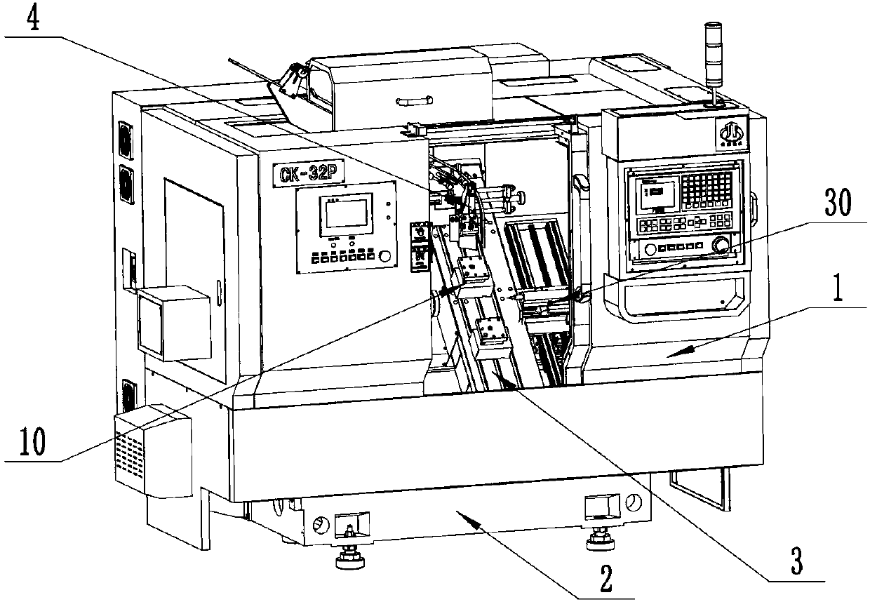
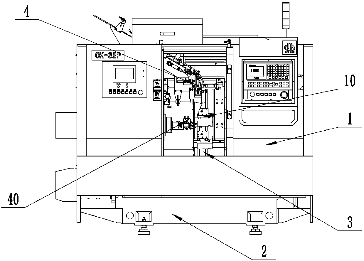
[0061] like figure 1 , figure 2 As shown in the figure, a special CNC lathe for processing engine valve sealing profiles, including a protective shell assembly 1, a bed base assembly 2, a sliding saddle assembly 3, a material distribution and discharge assembly 4, and a blanking assembly 5 , Spindle assembly, clamping and pushing assembly, pneumatic system assembly, lubrication system assembly, tool seat assembly 10, thimble assembly 30, spindle head rotating and feeding assembly 40,

[0062] The lower part of the bed base assembly 2 is fixedly connected to the ground, and the upper part is connected to the movable support of the sliding saddle assembly 3. The protective shell assembly 1 is supported by the bed base assembly 2 and is installed outside the machine body. The sliding saddle The upper part of the assembly 3 is detachably connected with the tool seat assembly 10, and the lower part of the tool seat assembly 10 corresponds to the main shaft assembly and the materi...


PUM


Abstract

The invention discloses a digital controlled lathe special for engine valve sealing molded line machining and a machining method of the digital controlled lathe. The digital controlled lathe comprisesa protection shell assembly, a lathe bed base assembly, a carriage assembly, a material dividing and emptying assembly, a discharging assembly, a main shaft assembly, a material clamping and pushingassembly, a pneumatic system assembly, a lubrication system assembly, a tool apron assembly, a centre assembly and a main shaft head rotating feeding assembly. All components are protected by the protection shell assembly and supported by the lathe bed base assembly, the carriage assembly achieves three-freedom-degree motion of a tool apron, the material dividing and emptying assembly achieves valve workpiece sorting and single discharging, the discharging assembly collects falling valve workpiece finished products, the centre assembly achieves clamping of auxiliary workpieces, workpieces automatically fall into a detachable main shaft head through the main shaft head rotating feeding assembly, the main shaft assembly drives the workpieces to rotate, the material clamping and pushing assembly clamps the workpieces and pushes out finished products, the pneumatic system assembly provides pneumatic force, the lubrication system assembly lubricates all relatively-moving components, and thetool apron assembly achieves clamping on a cutter. All assemblies are coordinated, and full-automatic efficienct production of an engine valve is achieved.

Description

technical field [0001] The invention relates to a special numerically controlled lathe, in particular to a special numerically controlled lathe for processing an engine valve sealing profile and a processing method thereof. Background technique [0002] The engine valve is a very important part in the engine, and its shape accuracy has a great impact on the performance of the engine. At the same time, with the continuous development of power machinery, the output requirements for engine valves are also increasing. In the current valve forming process, multiple machine tools are generally required for processing, such as chamfering, rough turning, semi-rough turning, fine turning, grinding and other processes. , dismantling tooling fixtures and other operations, the work of workers is boring and heavy. Even on CNC lathes, due to the particularity of the small processing surface, small volume and large number of valves, problems such as frequent loading and unloading, difficu...

Claims


Application Information

Patent Timeline
IPC IPC(8): B23B15/00B23B25/00B23B25/04B23Q1/01B23B1/00
Inventor 丁晓伟陈戌连
Owner ZHEJIANG JINTANG MACHINE TOOL
Why Eureka
Try Eureka