
High sensitivity receiving circuit applied to pulse laser radar system

A receiving circuit and laser radar technology, applied in radio wave measurement systems, instruments, etc., can solve the problems of limited dynamic range of variable gain amplifiers, large measurement errors, and rising costs, and achieve excellent practicability and economy, and wide input Dynamic range, the effect of eliminating walking errors

Active Publication Date: 2018-01-26
拓尔微电子股份有限公司
View PDF6 Cites 10 Cited by
  • Summary
  • Abstract
  • Description
  • Claims
  • Application Information

AI Technical Summary

Problems solved by technology

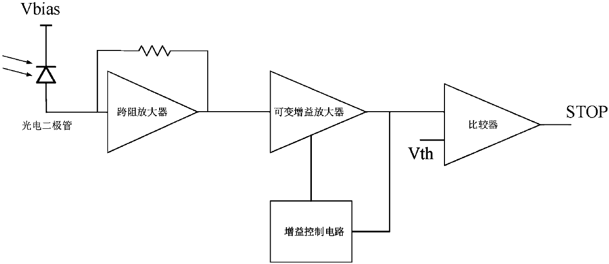
[0004] 1). The frontier time identification method cannot eliminate the walking error of the pulse echo signal, so the measurement error is often large;
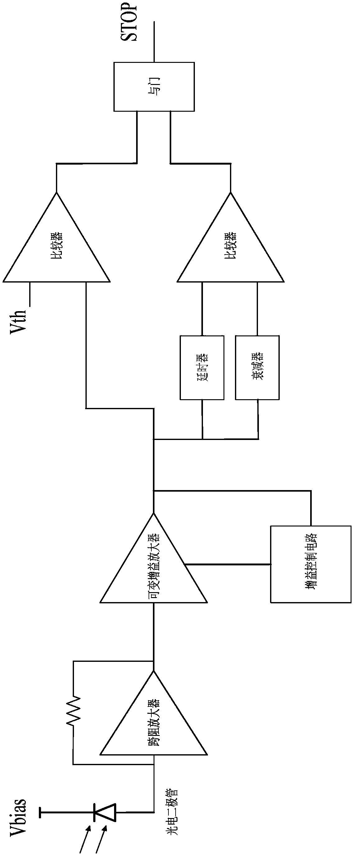
[0005] 2) The dynamic range of the variable gain amplifier is very limited and cannot achieve an ultra-wide dynamic range;
[0006] 3) Although the constant ratio identification method can eliminate the walking error, it needs to cooperate with an accurate delayer. A simpler delayer will lead to an increase in error, and an accurate delayer will lead to an increase in cost;
[0007] 4) The receiving circuit designed with transimpedance amplification often has large noise, so it is difficult to obtain high sensitivity

Method used


Image

  • High sensitivity receiving circuit applied to pulse laser radar system
  • High sensitivity receiving circuit applied to pulse laser radar system
  • High sensitivity receiving circuit applied to pulse laser radar system

Examples


Embodiment Construction

[0021] Attached as follows Figure 4 , to further describe the application scheme:

[0022] A high-sensitivity receiving circuit applied to a pulsed laser radar system, which includes a photodiode, a data selector, and a first channel and a second channel arranged between the two, and the photodiode is the signal acquisition input of the receiving circuit , the data selector is the signal output of the receiving circuit;

[0023] The first channel includes a channel selection switch S1, a transimpedance amplifier, mainly composed of a resistor R d and capacitance C d A first-order RC differential circuit, a voltage amplifier one, a zero-crossing comparator one and a threshold comparator one; the channel selector switch S1, a transimpedance amplifier, a first-order RC differential circuit, a voltage amplifier one and a zero-crossing comparator one in sequence connected, the input terminal of the threshold comparator one is connected to the output terminal of the voltage ampl...


PUM


Abstract

The invention provides a high sensitivity receiving circuit applied to a pulse laser radar system. The circuit herein includes a photodiode, a data selector and also a first channel and a second channel which are disposed between the photodiode and the data selector. The photodiode serves as signal sampling input of the receiving circuit. The data selector serves as signal output of the receivingcircuit. The first channel includes a channel selection switch S1, a trans-impedance amplifier, a first-order RC differentiating circuit, a voltage amplifier 1, a zero-crossing comparator 1 and a threshold comparator 1. The second channel includes a channel selection switch S2, a charge sense amplifier, a main second-order RC differentiating circuit, a voltage amplifier 2, a zero-crossing comparator 2, a threshold comparator 1 and a threshold comparator 2. According to the invention, the trans-impedance amplifier and the charge sense amplifier serve as pre-positioned amplifiers, so that low noise and ultra-wide dynamic range can be realized, the time discrimination circuit can be realized with the first-order and second-order differentiating circuits, the voltage amplifiers and zero-crossing comparators. The receiving circuit herein also reduces cost and ensures high precision.

Description

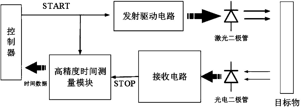
technical field [0001] The invention relates to a high-sensitivity receiving circuit applied to a pulse laser radar system. Background technique [0002] A pulsed laser radar system usually includes four parts: a controller, a transmitting drive circuit, a receiving circuit, and a high-precision time measurement module (refer to the attached figure 1 ), which uses the TOF (Time of Flight, time of flight) principle for distance measurement. Its working principle is: when the distance measurement starts, the controller sends a "START" signal to the emission drive circuit to drive the laser diode to emit narrow pulse laser. At the same time, the "START" signal also triggers the high-precision time measurement module to start timing; when the pulse After the laser is diffusely reflected by the target, the echo signal passes through the photodiode to generate a current pulse signal, and the signal is processed by the receiving circuit to generate a STOP signal. After receiving t...

Claims


Application Information

Patent Timeline
Patent Type & Authority Applications(China)
IPC IPC(8): G01S7/491
Inventor 郭建平李开友
Owner 拓尔微电子股份有限公司
Learn More