Liquid-gas separation method

A technology of liquid-gas separation and liquid-gas separator, which is applied in the field of oil drilling, can solve the problems of poor separation effect, difficult gas separation, low efficiency of liquid-gas separation, etc., to facilitate maintenance, promote liquid-gas separation, and enhance centrifugal separation effect of effect

Inactive Publication Date: 2018-01-30
CHENGDU ZHUOXIN IND
View PDF11 Cites 2 Cited by
  • Summary
  • Abstract
  • Description
  • Claims
  • Application Information

AI Technical Summary

Problems solved by technology

[0008] In the existing technology represented by the above-mentioned patent documents, the gas-invasion drilling fluid enters the tank from the liquid inlet pipe, and after colliding with the impact plate, it is scattered on a series of inner baffles. After the collision, the exposed surface area is increased, and it flows downward. The turbulent state is caused to break the large air bubbles and separate them from the drilling fluid. Although the gas-liquid mixing can be prevented to a certain extent, the gas-containing mud scattered on the inner baffle is relatively thick, and it is difficult to completely separate the gas from the mud. , the liquid-gas separation efficiency is low, and the separation effect is poor

Method used


Image

  • Liquid-gas separation method
  • Liquid-gas separation method
  • Liquid-gas separation method

Examples


Embodiment 1

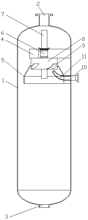
[0048] see figure 1 , a liquid-gas separation method, comprising the following steps:

[0049] a. Spray the gas-containing mud into the rotor of the liquid-gas separator through the inlet elbow 11 of the liquid-gas separator;

[0050] b. The gas-containing mud collides with the blades 9 in the rotor to disperse the gas-containing mud and perform the first liquid-gas separation;

[0051] c. The gas-containing mud pushes the rotor to rotate, and the gas-liquid is stratified under the action of centrifugal force, and the second liquid-gas separation is carried out;

[0052] d. The rotor rotates to throw out the air-containing mud, and evenly sprinkles it on the inner wall of the separation cover 5. The air-containing mud flows downward along the inner wall of the separation cover 5 under the action of gravity, forming an extremely thin cylindrical liquid film, and the air-containing mud The gas escapes from the cylindrical liquid film for the third liquid-gas separation;

[00...

Embodiment 2

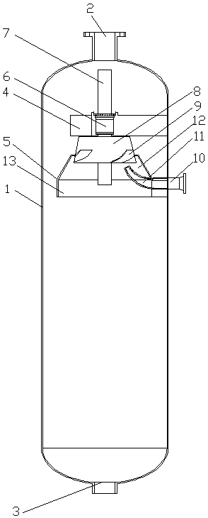
[0055] see figure 1 , a liquid-gas separation method, comprising the following steps:

[0056] a. Spray the gas-containing mud into the rotor of the liquid-gas separator through the inlet elbow 11 of the liquid-gas separator;

[0057] b. The gas-containing mud collides with the blades 9 in the rotor to disperse the gas-containing mud and perform the first liquid-gas separation;

[0058] c. The gas-containing mud pushes the rotor to rotate, and the gas-liquid is stratified under the action of centrifugal force, and the second liquid-gas separation is carried out;

[0059] d. The rotor rotates to throw out the air-containing mud, and evenly sprinkles it on the inner wall of the separation cover 5. The air-containing mud flows downward along the inner wall of the separation cover 5 under the action of gravity, forming an extremely thin cylindrical liquid film, and the air-containing mud The gas escapes from the cylindrical liquid film for the third liquid-gas separation;

[00...

Embodiment 3

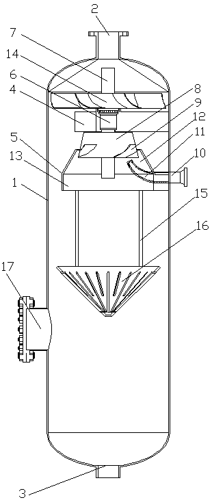
[0064] see figure 2 , a liquid-gas separation method, comprising the following steps:

[0065] a. Spray the gas-containing mud into the rotor of the liquid-gas separator through the inlet elbow 11 of the liquid-gas separator;

[0066] b. The gas-containing mud collides with the blades 9 in the rotor to disperse the gas-containing mud and perform the first liquid-gas separation;

[0067] c. The gas-containing mud pushes the rotor to rotate, and the gas-liquid is stratified under the action of centrifugal force, and the second liquid-gas separation is carried out;

[0068] d. The rotor rotates to throw out the air-containing mud, and evenly sprinkles it on the inner wall of the separation cover 5. The air-containing mud flows downward along the inner wall of the separation cover 5 under the action of gravity, forming an extremely thin cylindrical liquid film, and the air-containing mud The gas escapes from the cylindrical liquid film for the third liquid-gas separation;

[0...


PUM


Abstract

The invention discloses a liquid-gas separation method. The liquid-gas separation method is characterized by comprising the following steps that: a) gas-containing slurry is sprayed into a rotor of aliquid-gas separator; b) the gas-containing slurry collides with blades in the rotor to carry out primary liquid-gas separation; c) the gas-containing slurry pushes the rotor to rotate to carry out secondary liquid-gas separation; d) the rotor rotates to throw out the gas-containing slurry which is uniformly thrown on the inner wall of a separating hood, the gas-containing slurry flows downwards along the inner wall of the separating hood under the action of gravity to form an extremely-thin drum-shaped liquid film, and gas in the gas-containing slurry escapes from the drum-shaped liquid filmto carry out tertiary liquid-gas separation; e) the rotor rotates to drive the impeller integrated with the rotor to rotate so as to discharge gas in the liquid-gas separator, reduce the internal pressure of the liquid-gas separator and separate liquid and gas. The liquid-gas separation method disclosed by the invention has the advantages that by good matching of the rotor and the impeller, three-time liquid-gas separation can be realized, the gas in the gas-containing slurry can be thoroughly separated. The liquid-gas separation method has the characteristics of high liquid-gas separation efficiency and good separation effect.

Description

technical field [0001] The invention relates to the technical field of petroleum drilling, in particular to a liquid-gas separation method. Background technique [0002] The liquid-gas separator is the primary degassing equipment for gas-invasion drilling fluid, and it is a very useful mud-gas separator. According to the pressure, the liquid-gas separator can be divided into two types: normal pressure and pressure automatic control. [0003] The gas-invasion drilling fluid of the liquid-gas separator enters the separator tangentially from the liquid inlet of the separator, falls on a series of inner baffles along the inner wall, collides, increases the exposed surface area, and flows downward, causing a turbulent flow state, so that the gas and Drilling fluid separation. The free gas is discharged through the gas outlet on the top of the tank. The length of the exhaust pipe is determined and equipped on site, and is led to a safe place. The degassed drilling fluid is discha...

Claims


Application Information

Patent Timeline
Patent Type & Authority Applications(China)
IPC IPC(8): B01D19/00
Inventor 池振华卢伟肖吉华范俊
Owner CHENGDU ZHUOXIN IND
Why Eureka
Try Eureka