NMOS tube drive control circuit, chip, device and drive method

A drive control circuit and drive control technology, applied in applications, tobacco, smokers' products, etc., can solve the problems of rising on-resistance of power tubes, high prices, and changes in output power, and reduce on-resistance and conduction loss. , the circuit comprehensive cost is low, the effect of the booster circuit is simple

Pending Publication Date: 2018-02-02
SHENZHEN HOTCHIP TECH
View PDF7 Cites 7 Cited by
  • Summary
  • Abstract
  • Description
  • Claims
  • Application Information

AI Technical Summary

Problems solved by technology

The disadvantage is that the output is a square wave, the output power is easy to change with the battery voltage, and the grid is directly driven by the battery voltage. When the battery voltage drops, the conduction resistance of the power tube increases significantly, which affects the output efficiency.
Compared with NMOS power tubes, PMOS power tubes have the disadvantages of high price and high on-resistance
However, if an NMOS tube is used, since its gate can only be equal to the battery voltage BAT volts, in order to ensure that the power tube is turned on, the gate-source voltage must be maintained above 1 volt, that is, the load terminal can only be pulled up to (BAT-1 ) volts, otherwise the NMOS tube cannot be turned on, which means that the source and drain of the NMOS power tube are always subjected to a voltage drop of more than 1 volt. Such a voltage drop also makes the on-resistance large, which seriously affects the output power and efficiency

Method used


Image

  • NMOS tube drive control circuit, chip, device and drive method
  • NMOS tube drive control circuit, chip, device and drive method
  • NMOS tube drive control circuit, chip, device and drive method

Examples


Embodiment Construction

[0038] Embodiments of the present invention will be described in further detail below in conjunction with the accompanying drawings.

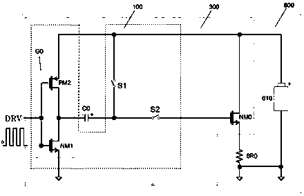
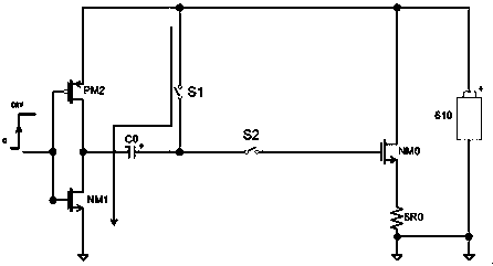
[0039] Such as Figures 2 to 4 The shown drive control circuit 100 for NMOS tube drive control includes a boost capacitor connection port for connecting to an external boost capacitor, and a port for electrically connecting the same source to the external NMOS tube that is grounded through the driven load. The drive port and the drive signal input port used to drive the control signal input; the two terminals of the boost capacitor connection port of the drive control circuit 100 are respectively used to electrically connect the positive and negative poles of the external boost capacitor; the drive control The two terminals of the drive port of the circuit 100 are respectively used to electrically connect to the gate and drain of the external NMOS transistor; the drive terminal used to connect to the drain of the external NMOS transistor is als...


PUM


Abstract

A NMOS tube drive control circuit, a chip, a device and a drive method are provided for driven loads and external power common ground application scenarios. A source of the NMOS tube is grounded through a driven load; a drain electrode of the NMOS tube is electrically connected with a positive electrode of an external power supply; a drive control module receives external drive control signals; the drive control module controls the gate potential of the NMOS tube to be converted to a potential higher than the gate drive potential threshold based on the external drive control signal; the gate drive potential threshold is the sum of the external supply voltage and the gate source open voltage of the external NMOS tube to guarantee the continuous drive capability of the NMOS tube. The invention is especially suitable for the application scenes where the electric heating wire of the electronic cigarette needs common ground with the battery. Compared with the PMOS drive, the cost and consumption are reduced and the method is economic and environmentally friendly.

Description

technical field [0001] The present invention relates to a drive control circuit and device based on MOS tubes; in particular, to a drive control circuit and device based on NMOS tubes, especially to an NMOS tube drive circuit and device when electronic cigarette heating wires and batteries are connected to a common ground. Background technique [0002] In the prior art, electronic cigarettes used for quitting smoking or replacing cigarettes generally include a pipe containing nicotine or a replacement solution, an atomization heating device for atomizing and heating the nicotine or replacement solution, and a device for powering the device. Battery. The atomization heating device can convert the liquid nicotine or alternative solution in the pipe into a mist and heat it to a certain temperature, so that the user has a smoking-like feeling when inhaling, and realizes "swallowing". [0003] In the practical application of electronic cigarettes, multi-section metal smoke tubes...

Claims


Application Information

Patent Timeline
IPC IPC(8): A24F47/00
CPCY02B70/10
Inventor 张海波柏志彬李盛峰
Owner SHENZHEN HOTCHIP TECH
Why Eureka
Try Eureka