Pressurized water nuclear reactor nested component

A nuclear reactor and nested technology, applied in the field of nuclear power, can solve problems such as difficult to eliminate coolant turbulence and turbulent eddy current, unsatisfactory flow distribution effect, and coolant flow attenuation, so as to achieve stable and uniform coolant, simple structure, and low Attenuation effect

Pending Publication Date: 2018-02-02
NUCLEAR POWER INSTITUTE OF CHINA
View PDF3 Cites 2 Cited by
  • Summary
  • Abstract
  • Description
  • Claims
  • Application Information

AI Technical Summary

Problems solved by technology

A variety of flow distribution devices have been disclosed in the prior art. In order to overcome the problems of complex structure, unsatisfactory flow distribution effect and difficult installation and maintenance of the traditional flow distribution device with orifice structure, the structure of the flow distribution device has been adopted in recent years. The form of porous bowl structure is the main form (see ZL201210126989.1, ZL201210137211.0, ZL201410188559.1), although the flow distribution device of this type of structure simplifies the structure, improves the uniformity of flow distribution, and is easy to replace and repair, but There are also the following deficiencies: the flow rate of the coolant at the edge of the core inlet has a large attenuation; it is difficult to eliminate the movement and disturbance of the coolant in the lower chamber and the eddy current caused by the concave structure of the lower head; , the amount of metal melted by the flow distribution device is too small

Method used


Image

  • Pressurized water nuclear reactor nested component
  • Pressurized water nuclear reactor nested component
  • Pressurized water nuclear reactor nested component

Examples


Embodiment 1

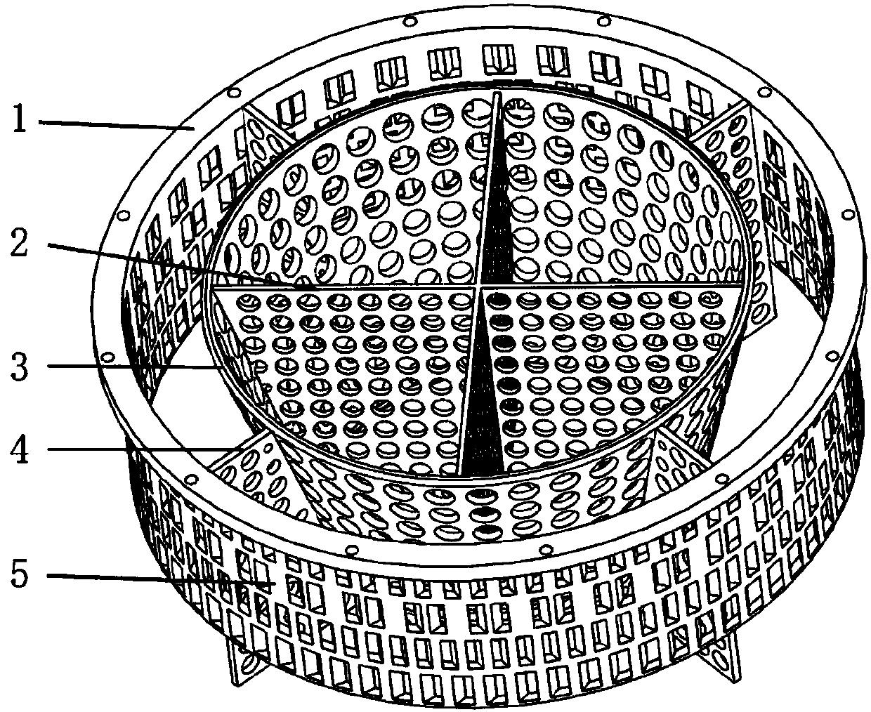
[0034] In this embodiment, the nested components of the pressurized water nuclear reactor are such as figure 1 As shown, it is composed of an inner flow distribution cylinder 3 , an outer flow distribution cylinder 5 , an outer flow distribution plate 4 , an inner flow distribution plate 2 and an outer flange 1 .

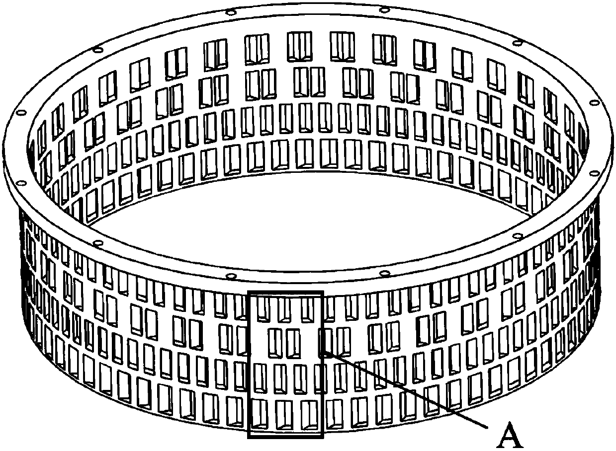
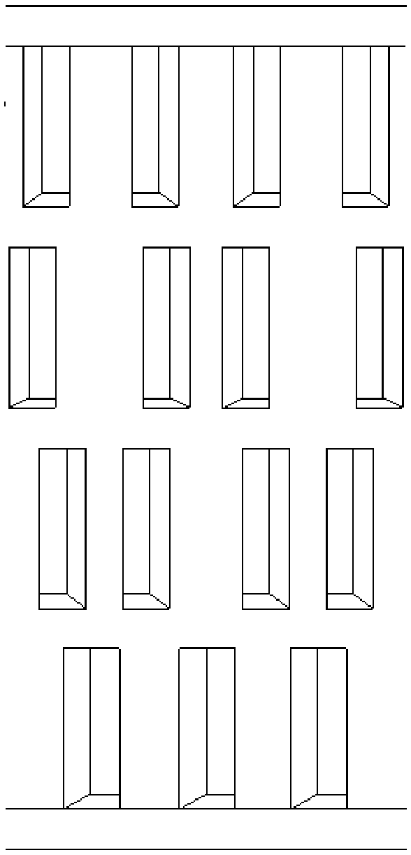
[0035]The outer flow distribution cylinder 5 is as figure 2 As shown, it is a cylinder with openings at both ends, and a plurality of flow holes are arranged on the wall of the cylinder. The flow holes are arranged in a four-layer ring, and the total water flow area of ​​each layer of flow holes increases sequentially from the upper layer to the lower layer; image 3 As shown, the shape of the flow holes of each layer is rectangular. From top to bottom, the opening directions of the adjacent two flow holes of the first layer and the second layer are staggered to form a certain angle, and the opening directions of the flow holes of the third layer and the fourth lay...

Embodiment 2

[0042] In this embodiment, the nested components of the pressurized water nuclear reactor are such as Figure 6 As shown, it is composed of an inner flow distribution cylinder 3 , an outer flow distribution cylinder 5 , an outer flow distribution plate 4 , an inner flow distribution plate 2 and an outer flange 1 .

[0043] The difference from Example 1 is: (1) the inner layer flow distribution cylinder 3 is a cylinder with openings at both ends; (2) the outer layer flow distribution plate 4 and the inner layer flow distribution plate 2 are rectangular plates; (3) The height of the outer layer flow distribution cylinder 5 is the same as that of the inner layer flow distribution cylinder 3, and after combination, the distance between the inner layer flow distribution cylinder 3 and the outer layer flow distribution cylinder 5 is 500 mm.

Embodiment 3

[0045] In this embodiment, the nested components of the pressurized water nuclear reactor are such as Figure 7 As shown, it is composed of an inner flow distribution cylinder 3 , an outer flow distribution cylinder 5 , an outer flow distribution plate 4 , an inner flow distribution plate 2 and an outer flange 1 .

[0046] The difference from Example 1 is: (1) the outer flow distribution cylinder 5 is a truncated conical cylinder with openings at both ends, a large top and a small bottom, and the taper is the same as that of the inner flow distribution cylinder 3; (2) the outer layer The total water flow area of ​​each layer of flow holes of the flow distribution cylinder 5 is the same; (3) the height of the outer layer flow distribution cylinder 5 is the same as the height of the inner layer flow distribution cylinder 3. After combination, the inner layer flow distribution cylinder 3 and the outer layer The distance between the flow distribution cylinders 5 is 600mm.


PUM


Abstract

A pressurized water nuclear reactor nested component comprises an inner-layer flow distributing barrel, an outer-layer flow distributing barrel and at least three outer-layer flow distributing plates.Multiple water flowing holes are formed in the wall of each of the inner-layer flow distributing barrel and the outer-layer flow distributing barrel, an outer flange connected with a reactor core lower supporting plate is arranged at the upper end of the outer-layer flow distributing barrel, and multiple water flowing holes are formed in the surface of each plate; the inner-layer flow distributing barrel is put in an inner cavity of the outer-layer flow distributing barrel, central lines of the inner-layer flow distributing barrel and the outer-layer flow distributing barrel are coincident, the outer-layer flow distributing plates are in dispersed arrangement in an annular space surrounded by the outer wall of the inner-layer flow distributing barrel and the inner wall of the outer-layerflow distributing barrel, and two side faces of each outer-layer flow distributing plate are fixedly connected with the outer wall of the inner-layer flow distributing barrel and the inner wall of theouter-layer flow distributing barrel. The nested component is used for coolant flow distributing, attenuation of coolant flow at the edge of a reactor core inlet can be reduced, displacement and disturbance of a coolant in a lower cavity are prevented, vortex is suppressed, and quantity of metal obtained by melting is increased.

Description

technical field [0001] The invention belongs to the technical field of nuclear power, and relates to a component (or device) installed in a lower chamber of a pressurized water type nuclear reactor and suitable for coolant flow distribution. Background technique [0002] The role of the reactor in a nuclear power plant is like that of a hydroelectric generator set in a hydropower plant. It can be said that it is the heart of the entire nuclear power plant system. Among them, the nuclear fuel maintains a controllable chain fission reaction inside the reactor. The energy generated by nuclear fission increases the temperature of the coolant flowing through the reactor, and then the heat is exported from the core through the coolant circulation loop. During this process, the distribution uniformity coefficient of the reactor coolant in the core will directly affect the temperature distribution of the core, and at the same time have an important impact on key safety parameters of...

Claims


Application Information

Patent Timeline
Patent Type & Authority Applications(China)
IPC IPC(8): G21C15/12G21C15/18
CPCG21C15/12G21C15/18Y02E30/30
Inventor 李文强赵玉东李彦李飞李松韩怀邦刘启虞冉仁杰
Owner NUCLEAR POWER INSTITUTE OF CHINA
Why Eureka
Try Eureka