

Temperature and humidity uniformity reinforced fuel cell single cell and electric pile
A fuel cell and single cell technology, applied in fuel cells, fuel cell additives, fuel cell heat exchange, etc. Large field resistance and other problems, to achieve the effect of improving work performance and use stability, avoiding uneven temperature distribution, and improving uniformity
- Summary
- Abstract
- Description
- Claims
- Application Information
AI Technical Summary
Problems solved by technology
Method used
Image

Examples
Embodiment 1
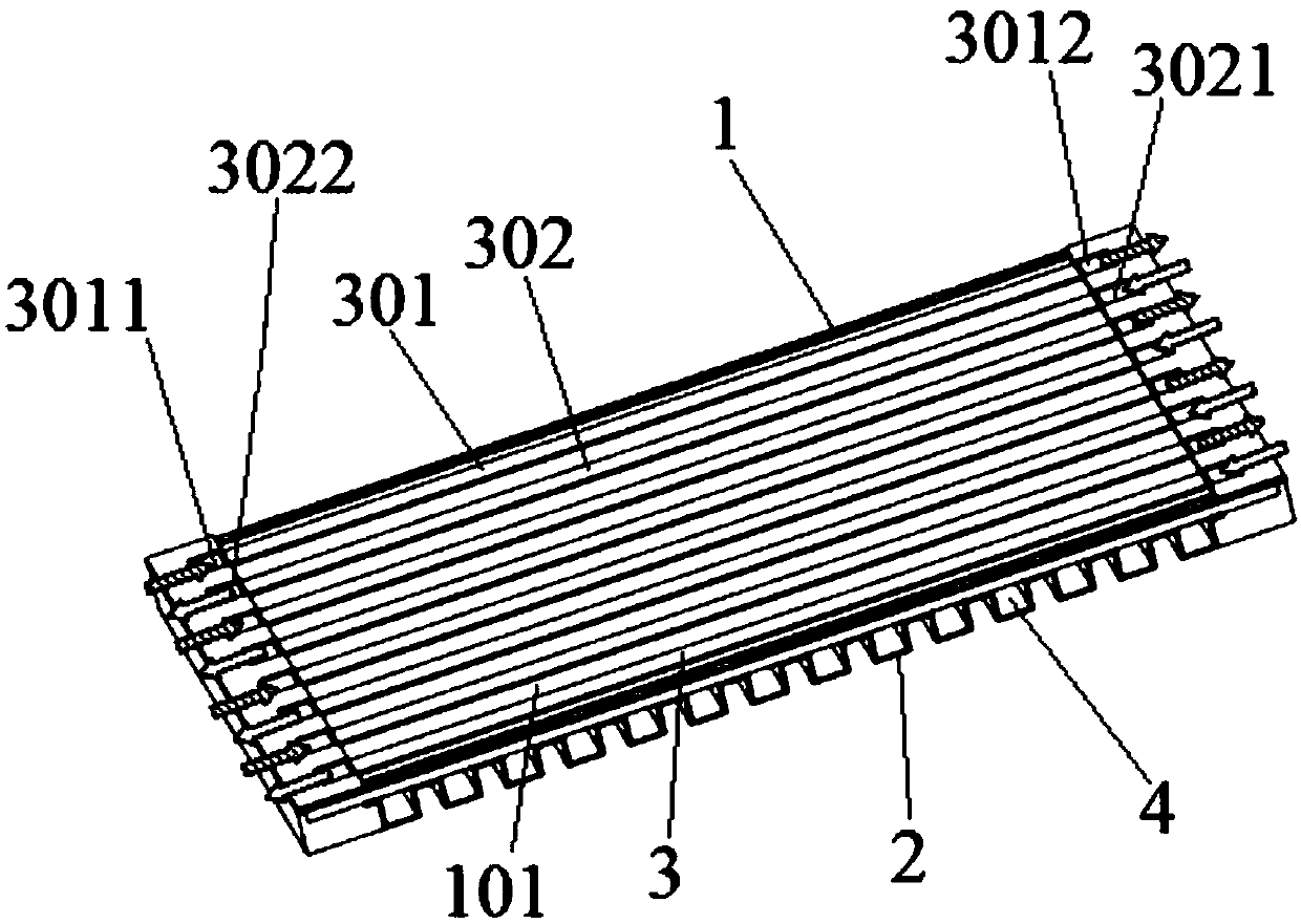
[0039] Such as figure 1 A single fuel cell with enhanced temperature and humidity uniformity is shown, the single cell includes an anode plate 1, a cathode plate 2, and a membrane electrode assembly arranged between the anode plate 1 and the cathode plate 2, and the anode plate A plurality of anode flow channels 3 are arranged side by side on the plate 1 , the gas flow directions in two adjacent anode flow channels 3 are opposite, and a cathode flow channel 4 is provided on the cathode plate 2 .
[0040] Wherein, the anode electrode plate 1 and the cathode electrode plate 2 are both punched and formed by a stainless steel sheet with a thickness of 0.1 mm, and punched and trimmed. The anode plate 1 and the cathode plate 2 are assembled and bonded together and then laser welded to form a bipolar plate. The cathode flow channel 4 and the anode flow channel 3 are perpendicular to each other. An anode flow channel partition 101 is provided between two adjacent anode flow channels...
Embodiment 2
[0046] A single fuel cell with enhanced temperature and humidity uniformity, the single cell includes an anode plate 1, a cathode plate 2, and a membrane electrode assembly arranged between the anode plate 1 and the cathode plate 2, the anode plate 1 A plurality of anode flow channels 3 are arranged side by side, the gas flow directions in two adjacent anode flow channels 3 are opposite, and the cathode plate 2 is provided with a cathode flow channel 4 .
[0047] Wherein, the cathode flow channel 4 and the anode flow channel 3 are perpendicular to each other. An anode flow channel partition 101 is provided between two adjacent anode flow channels 3 .
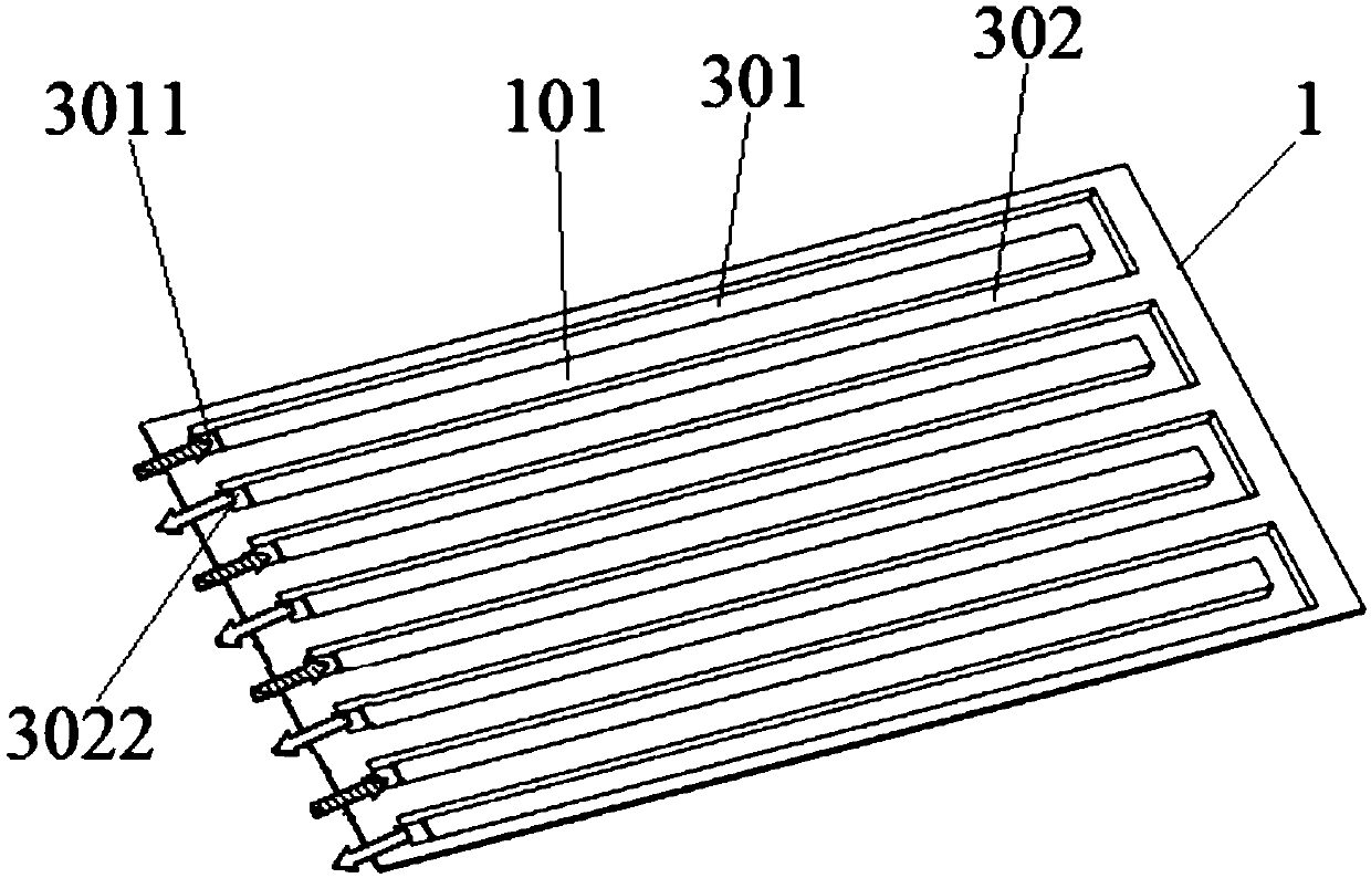
[0048] On the anode plate 1, a plurality of first anode flow channels 301 and second anode flow channels 302 are arranged alternately in sequence along the width direction of the anode plate 1, and one end of the anode plate 1 is provided with a bridge connected to the first anode flow channel 301. The first anode flow channel ...
PUM
 Abstract
Description
Claims
Application Information