
Software-defined network-based virtual network control method and device

A virtual network control and software-defined network technology, applied in the field of virtual network, can solve the problems of data center configuration complexity, loss, and network configuration can not be fully automated, and achieve the effect of huge scale, high performance and stability

Active Publication Date: 2018-02-06
BEIJING KINGSOFT CLOUD NETWORK TECH CO LTD +1
View PDF8 Cites 9 Cited by
  • Summary
  • Abstract
  • Description
  • Claims
  • Application Information

AI Technical Summary

Problems solved by technology

[0006] The configuration of the related data center is complicated, maintenance is difficult, and the flexibility is poor. The modification of the network is often very huge due to slight changes in the network requirements, and because the equipment operation commands of different models and manufacturers are generally different, the network configuration cannot be completely completed. Realizing automation requires someone to intervene, which often leads to unnecessary losses due to negligence in operation and wrong configuration
The network architecture of traditional data centers can no longer meet the needs of automation and flexible customization of network control

Method used


Image

  • Software-defined network-based virtual network control method and device
  • Software-defined network-based virtual network control method and device
  • Software-defined network-based virtual network control method and device

Examples


Embodiment 1

[0106] Such as Figure 4 As shown, the data center network in this embodiment takes a three-layer network as an example. The middle two layers are full mesh-connected networks that can provide non-blocking forwarding, and the access layer devices are dual uplinked to the middle aggregation layer network. For example, the topology of a layer of P devices is also supported.

[0107] The P device can use a 32*40G DC (data center) Core, and the PE device can use a 48*10G+4*40G TOR. This topology uses 48 DC Cores and 128 TORs to provide a maximum of 3:1 convergence. 6144 10GE access ports are connected to the x86 server below, and a vswitch runs on the server for forwarding. In this topology scale, according to the server configuration of 24 cores and 128G memory, it can roughly provide services for about 100,000 virtual machines.

[0108] In this system, the upper two-layer switch acts as a P device and uses the outer label (Tunnel label) of mpls to forward, and each P and PE dev...

Embodiment 2

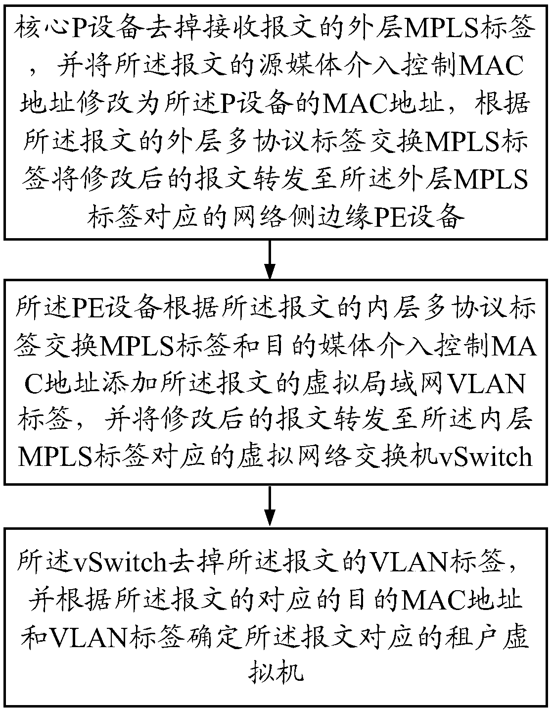
[0114] P equipment processing flow

[0115] 1. Message processing flow between P devices

[0116] The packet received by the P device is an mpls packet with a double-layer label. The destination mac of the packet plus the default vid (vlan id) of the port is searched and then forwarded by mpls. Match the outer tunnel label to find the egress and modify the front of the label The source mac is the system mac of the P device, the destination mac and tag are not modified, and the modified message is sent from the egress in the form of untag. If SourcePort is 0, it means that the source port does not need to be matched.

[0117] The corresponding openflow flow table matches and actions are:

[0118] Match: DMac+SourcePort+Tunnel Label(mpls tag)

[0119] Action: DestPort+Set SMac

[0120] The corresponding openflow interfaces can be deduced from the message processing flow, and will not be described in detail.

[0121] 2. The message processing flow sent by the P device to the...

Embodiment 3

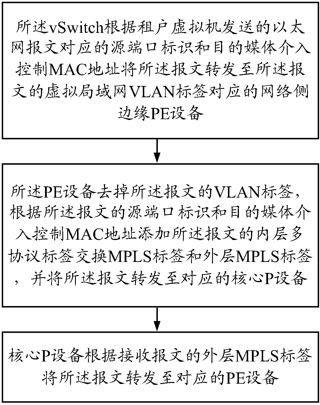
[0124] PE device Layer 2 packet processing flow

[0125] 1. L2 (Layer 2 message) ingress (uplink, incoming PE device) message processing flow

[0126] The packet received by the PE device is an Ethernet packet with a VDid (virtual device id, vlan id, which distinguishes the vrouter and vbridge devices in the virtual network), and the PE device assigns an SVp to the packet according to the SourcePort and VDid and obtains the VFI According to DMac+VFI, look up the mac entry to get the two-layer label that needs to be added to the message (the Tunnel Label is the Label representing the destination PE, and the inner label is the inner Label representing the tenant) and egress, the destination mac of the second-layer header before the label It is the unified mpls layer 2 header mac, the source mac is the system mac of the device, the EtherType is mpls type 0x8847, and the modified message is sent from the egress in untag format.

[0127] 2. L2egress message processing flow

[012...


PUM


Abstract

The invention relates to a software-defined network-based virtual network control method and device and belongs to the virtual network field. The method includes the following steps that: core P devices remove the outer-outer MPLS labels of received messages, the source media intervention control MAC addresses of the messages are modified into the MAC address of P devices, the modified messages are forwarded to network side provider edges (PE) corresponding to the outer-outer MPLS labels according to the outer-layer multi-protocol label switching (MPLS) labels of the messages; the PEs add thevirtual local area network (VLAN) labels of the messages according to the inner-layer multi-protocol label switching (MPLS) labels and destination media intervention control MAC addresses of the messages and forward the modified messages to virtual network switches (vSwitch) corresponding to the inner-layer MPLS labels; and the virtual network switches (vSwitch) remove the VLAN labels of the messages and determine tenant virtual machines corresponding to the messages according to the corresponding destination MAC addresses and VLAN labels of the messages.

Description

technical field [0001] The invention relates to the field of virtual networks, in particular to a virtual network control method and device based on a software-defined network (SDN). Background technique [0002] In recent years, the traditional network architecture is no longer sufficient to meet people's flexible and complex network requirements. Existing network solutions are often too complex and costly to maintain. The concept of SDN (Software Define Network, Software Defined Network) has emerged and gained a lot of attention. Acclaimed by industry insiders. The core idea of ​​SDN is software programmable, which separates network control and forwarding. It has changed the design of the traditional network distributed system, centralized the control layer logic of the network to the SDN controller for management and maintenance, greatly reduced the management complexity of the network, and liberated the operation and maintenance personnel. At the same time, the network ...

Claims


Application Information

Patent Timeline
IPC IPC(8): H04L12/723H04L12/741H04L45/50H04L45/74
CPCH04L45/50H04L45/74
Inventor 周帅
Owner BEIJING KINGSOFT CLOUD NETWORK TECH CO LTD
Learn More