Back Contact Perovskite Solar Cell

Inactive Publication Date: 2015-12-31
SHARP KK
View PDF1 Cites 17 Cited by
  • Summary
  • Abstract
  • Description
  • Claims
  • Application Information

AI Technical Summary

Benefits of technology

[0012]Disclosed herein is a new cell architecture that takes full advantage of the material properties of hybrid organic/inorganic perovskite. Hybrid organic/inorganic perovskite (i.e. a perovskite comprised of both organic and inorganic materials) performs well as an (optical) absorber material, but also exhibits high carrier mobility. In fact, a mixed iodide/chloride of hybrid perovskite has demonstrated extremely high mobilities for both carriers with a diffusion length approaching about 1 micron. The long carrier diffusion length permits the perovskite solar cell to be enabled in a backside contacting architecture by placing both n- and p-type semiconductors under the absorber (perovskite) layer. Thus, the n- and p-type semiconductors, which respectively function as hole and electron blocking layers, can establish an internal

Problems solved by technology

Thirdly, in such a backside architecture there are no top electrode and metal grids to blo

Method used


Image

  • Back Contact Perovskite Solar Cell
  • Back Contact Perovskite Solar Cell
  • Back Contact Perovskite Solar Cell

Examples


Embodiment Construction

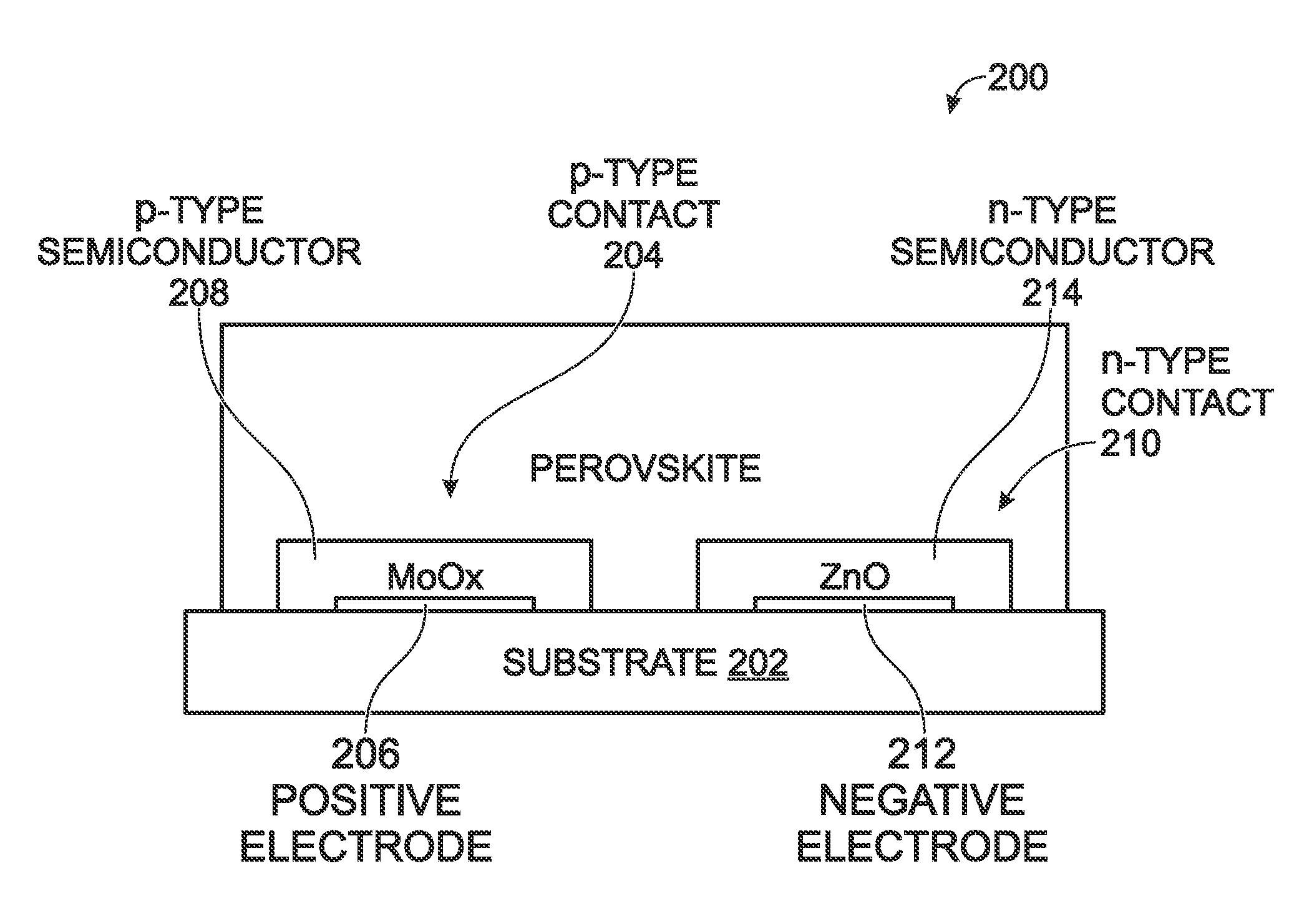
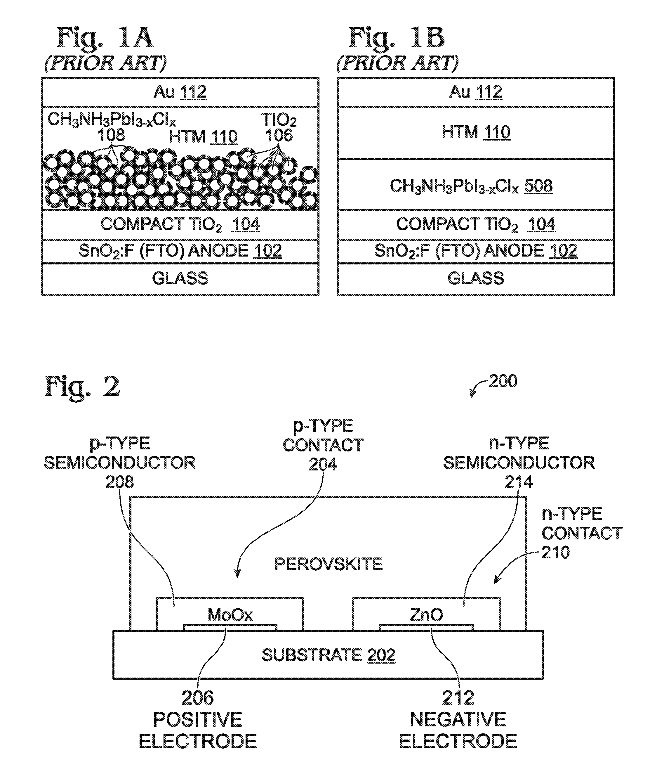
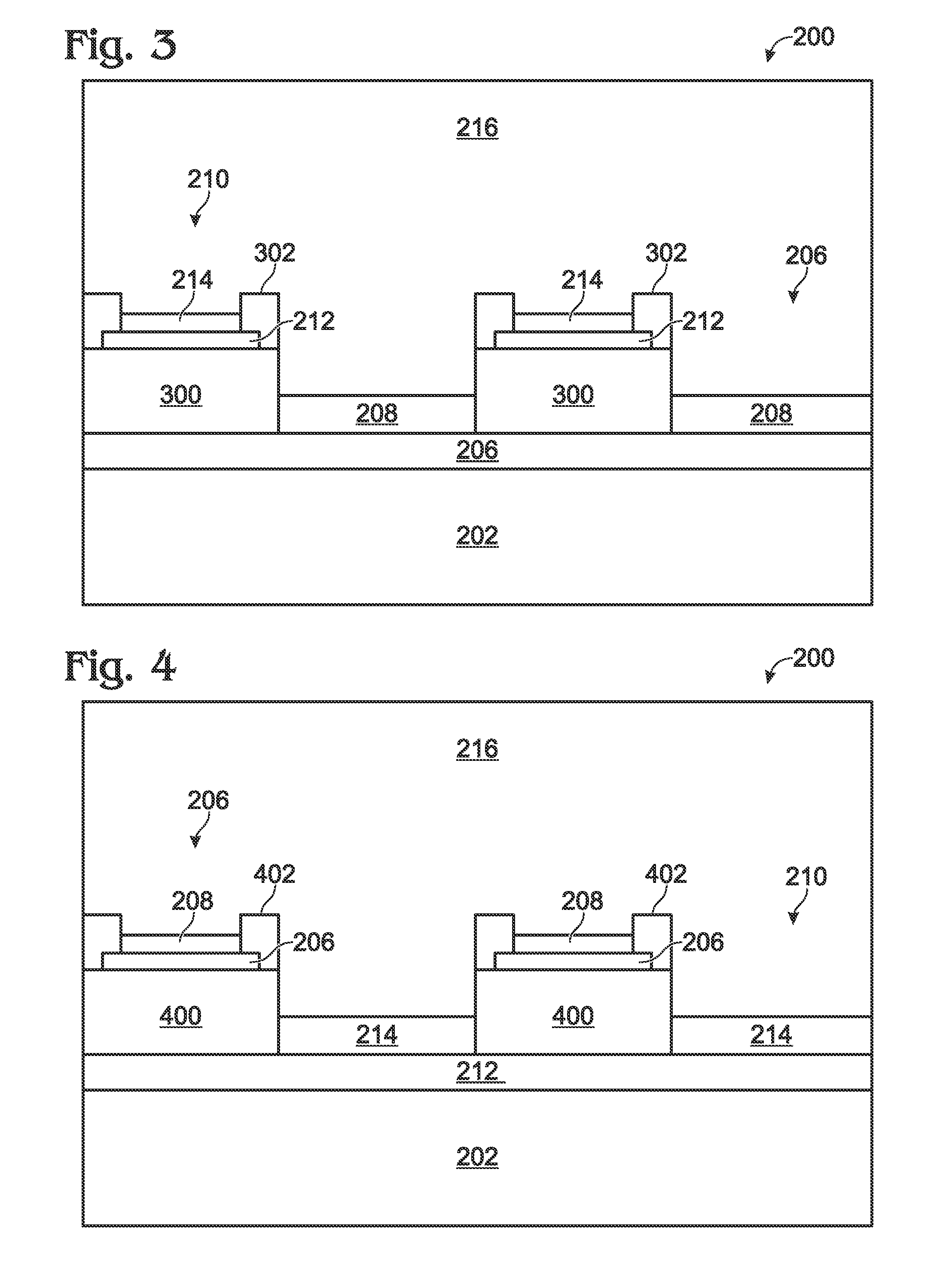
[0024]FIG. 2 is a partial cross-sectional view of a back contact perovskite solar cell. The solar cell 200 comprises a substrate 202 with a plurality of p-type contacts 204 overlying the substrate. For simplicity, only one p-type contact 204 is shown. Each p-type contact 204 comprises a positive electrode 206 and a p-type semiconductor segment 208 overlying the positive electrode 206. A plurality of n-type contacts 210 also overlies the substrate 202. Again, for simplicity, only one n-type contact 210 is shown. Each n-type contact 210 comprises a negative electrode 212 and an n-type semiconductor segment 214 overlying the negative electrode. A hybrid organic / inorganic perovskite layer 216 overlies the p-type contacts 204 and n-type contacts 210.

[0025]In such a cell 200, the absorption of photons by the hybrid perovskite material 216 is followed by the formation and dissociation of excitons. The separated charges move towards the contact areas, as the nature of the n- and p-type semi...


PUM


Abstract

A method is provided for forming a back contact perovskite solar cell. A substrate is coated with a positive electrode layer. The positive electrode layer is then conformally coated with a first insulator. A plurality of negative electrode segments are selectively deposited overlying the first insulator layer, and a second insulator layer is conformally deposited overlying the negative electrode segments and first insulator layer. The second insulator layer is selectively etched to expose the negative electrode segments, and an n-type semiconductor is selectively deposited overlying each exposed negative electrode segment to form n-type contacts. The first and second insulator layers are then selectively etched to expose positive electrode segments. A p-type semiconductor is selectively deposited over each exposed positive electrode segment to form p-type contacts. Finally, a hybrid organic/inorganic perovskite (e.g., CH3NH3Pbl3-XClX) layer is conformally deposited overlying the p-type and n-type contacts. A back contact solar cell is also provided.

Description

RELATED APPLICATIONS[0001]This application is a Continuation-in-part of a patent application entitled, MESOPOROUS STRUCTURE SOLAR CELL WITH SILOXANE BARRIER, invented by Alexey Koposov et al., Ser. No. 14 / 320,702, filed Jul. 1, 2014, attorney docket No. SLA3390;[0002]This application is a Continuation-in-part of a parent application entitled, PLANAR STRUCTURE SOLAR CELL WITH INORGANIC HOLE TRANSPORTING MATERIAL, invented by Alexey Koposov et al., Ser. No. 14 / 320,691, filed Jul. 1, 2014, attorney docket No. SLA3386.[0003]which is a Continuation-in-part of a patent application entitled, SURFACE-PASSIVATED MESOPOROUS STRUCTURE SOLAR CELL, invented by Changqing Zhan et al., Ser. No. 14 / 320,488, filed Jun. 30, 2014, attorney docket No. SLA3383. All these applications are incorporated herein by reference.BACKGROUND OF THE INVENTION[0004]1. Field of the Invention[0005]This invention generally relates to solar cells and, more particularly, to a back contact solar cell using a hybrid organic...

Claims


Application Information

Patent Timeline
IPC IPC(8): H01L51/42H01L51/00H01L51/44
CPCY02E10/549H01L51/4213H01L51/4233H01L51/0017H01L51/441H10K71/231H10K30/152H10K30/10H10K30/81H10K85/50
Inventor KOPOSOV, ALEXEYPAN, WEI
Owner SHARP KK
Why Eureka
Try Eureka