Cloth sponge compounding machine

A composite machine and fabric technology, applied in the field of composite machines and fabric sponge composite machines, can solve the problems of uneven alignment of fabric and sponge, uneven product edge thickness, and low product qualification rate, so as to reduce the degree of deviation and improve Cutting effect, effect of improving flatness

Active Publication Date: 2018-02-09
HIGHER TECH CO LTD
View PDF10 Cites 2 Cited by
  • Summary
  • Abstract
  • Description
  • Claims
  • Application Information

AI Technical Summary

Problems solved by technology

[0004] The above-mentioned solution can solve the deficiencies of the existing composite machine, but it has not solved the following problems: 1. The composite cloth and sponge are not aligned on the same side, resulting in a low pass rate of the composite product; 2. The cloth is prone to edge curling, resulting in The edge thickness of the product is uneven and incomplete; 3. The edge burrs of the compounded product are more, and the product quality is poor

Method used


Image

  • Cloth sponge compounding machine
  • Cloth sponge compounding machine
  • Cloth sponge compounding machine

Examples


Embodiment 1

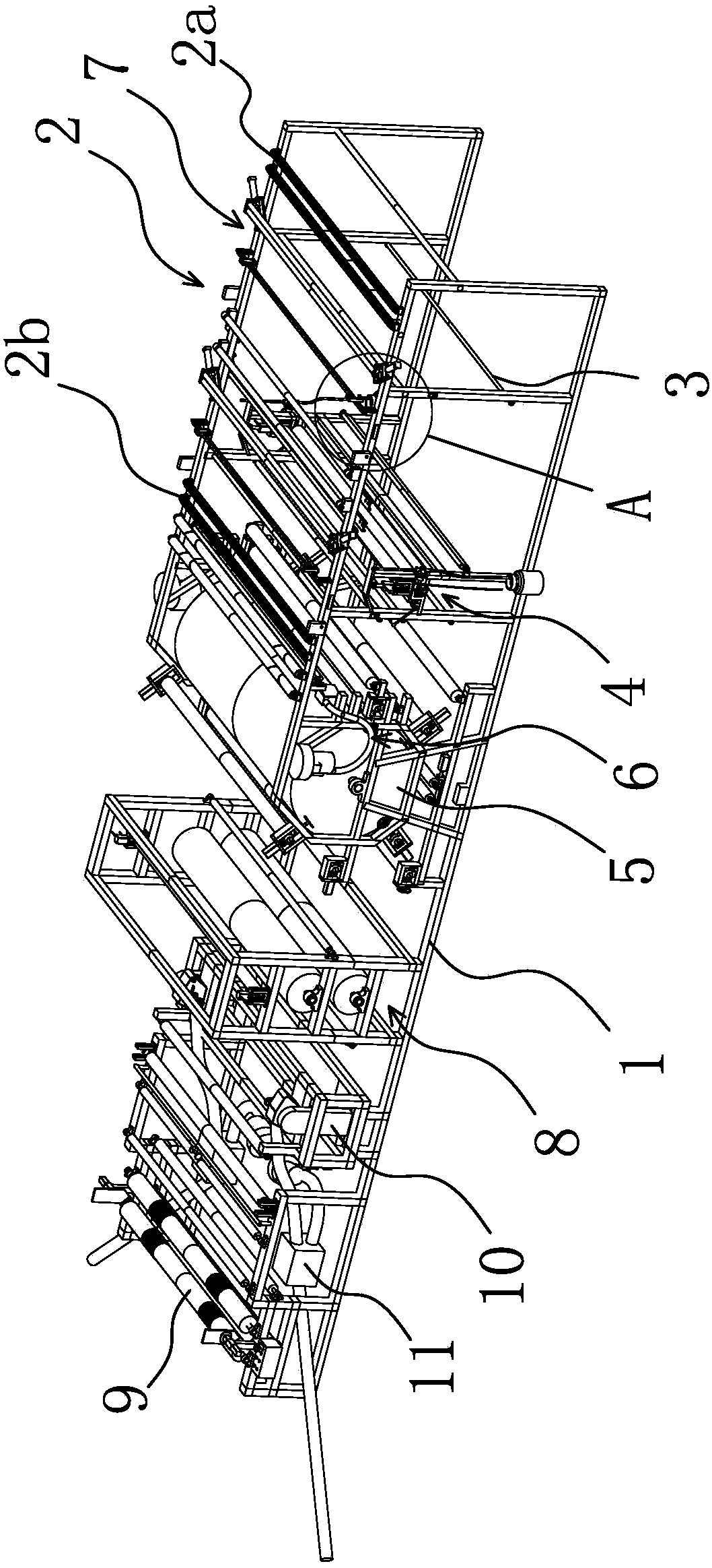
[0047] like figure 1 As shown, the fabric and sponge composite machine includes a frame 1, a fabric feeding device 2 is arranged above the front end of the frame 1, and a sponge roll holder 3, a gluing device 4, and a cloth feeding device 2 are arranged below the fabric feeding device 2. The rear is provided with thermal lamination device 5, and both sides of frame 1 are respectively provided with an anti-curl device 6, and anti-curl device 6 is positioned between cloth feeding device 2 and thermal lamination device 5, and the machine of thermal lamination device 5 rear Cooling device 8 trimming device 10 and take-up device 9 are arranged successively on frame 1, and trimming device 10 is arranged on frame 1 both sides respectively, and trimming device 10 can carry out trimming to finished cloth; A receiving device 11 is arranged. The cloth enters the anti-curling device 6 through the cloth feeding device 2, and the edge of the cloth is unfolded by the anti-curling device 6, ...

Embodiment 2

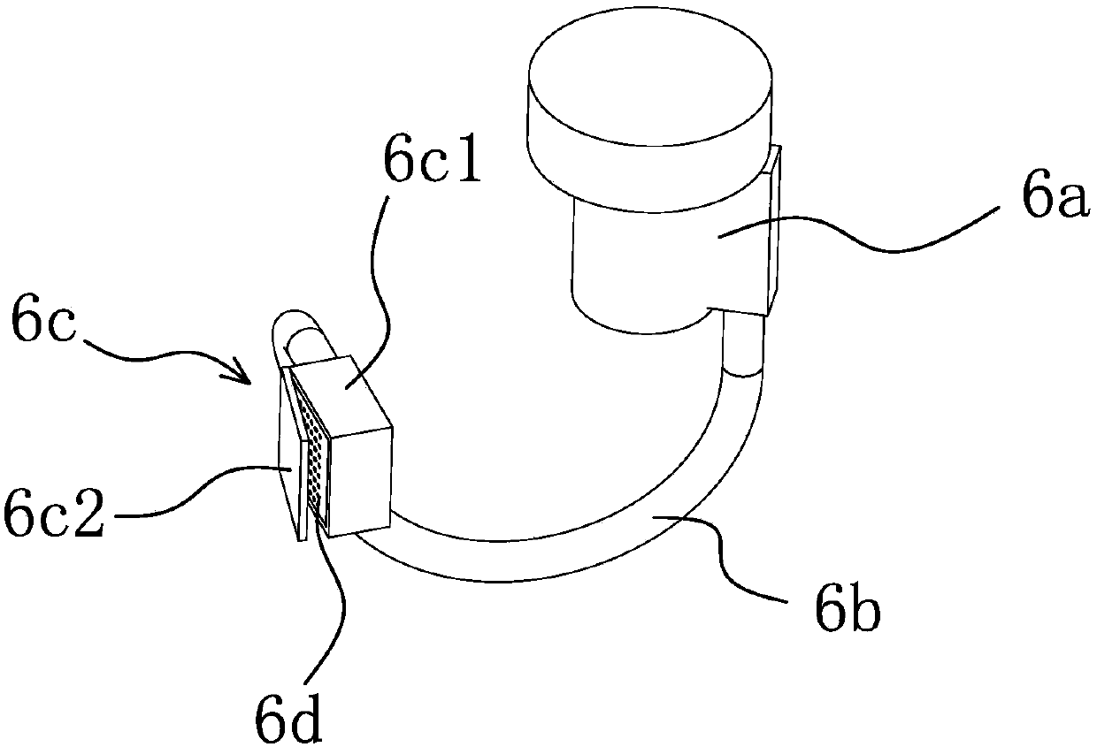
[0056] In this embodiment, the basic mechanism of the fabric and sponge composite machine is the same as that of Embodiment 1. The difference lies in: Figure 10As shown, the air outlet assembly 6c includes two opposite air boxes 6c1, and there is a gap between the two air boxes 6c1 for the edge of the cloth to pass through, that is, the two air boxes 6c1 are respectively located on both sides of the cloth advancing path. The side wall of each bellows 6c1 close to the cloth side is provided with some air outlets to form air outlets 6d, and each air outlet is inclined from the side of the bellows 6c1 near the center of the frame 1 to the side of the bellows 6c1 near the edge of the frame 1. When the fabric passes through the bellows 6c1, the wind blown by fan 1 6a enters the bellows 6c1 through the ventilation pipe 6b, and then blows out through the air outlet. The air outlet of the bellows blows air, no matter which side the edge of the fabric is bent, it can be blown flat by ...


PUM


Abstract

The present invention provides a cloth sponge compounding machine, belongs to the technical field of machinery, and solves the problems that folds and turned edges are easy to produce when cloth and sponge are compounded in the prior art. The cloth sponge compounding machine comprises a frame, a cloth feeding device is arranged above the front end of the frame, a thermal compounding device is arranged at the back of the cloth feeding device, each of the two sides of the frame is provided with an anti-curling device, each anti-curling device is located between the cloth feeding device and the thermal compounding device, each anti-curling device comprises a fan I, a venting tube and an air-out component, the air-out component is in communication with the fan I through the venting tube, the air-out component is arranged at a position near the edge of a cloth feeding path on the frame, and the air-out component is provided with an air outlet facing the edge of the cloth feeding path. By use of the cloth sponge compounding machine, the edge of a compounded cloth finished product is neat and regular, and processing efficiency is high.

Description

technical field [0001] The invention belongs to the technical field of machinery, and relates to a composite machine, in particular to a fabric and sponge composite machine. Background technique [0002] With the development of social economy, coating compound machine is more and more widely used. At present, when the sponge is combined with the cloth, because the sponge is relatively easy to break, and the cloth is easy to be deformed, the transmission mechanism of the existing coating compound machine is transmitted by pulling the material itself, and it is always with tension when conveying the material. During transportation, the sponge will be broken and the cloth will be deformed. Therefore, the existing coating compound machine cannot be used to compound the sponge roll material and the cloth roll material. Labor and energy costs are high, the composite material is uneven, the quality of the composite material is poor, and the amount of glue is relatively large, whic...

Claims


Application Information

Patent Timeline
Patent Type & Authority Applications(China)
IPC IPC(8): B32B37/06B32B37/08B32B37/10B32B37/12B32B38/00B32B5/18
CPCB32B5/18B32B37/06B32B37/08B32B37/10B32B37/12B32B38/0012B32B38/04B32B2038/045
Inventor 许斌
Owner HIGHER TECH CO LTD
Why Eureka
Try Eureka