
Hole interior variable-frequency vibration anti-reflection gas extraction method and device

A technology of variable frequency vibration and gas extraction, which is applied in vibration generating devices, gas discharge, safety devices, etc., can solve the problems of low extraction efficiency, limited application scope, pollution, etc., and achieve the effect of broadening the application scope.

Active Publication Date: 2018-02-09
SICHUAN UNIV
View PDF3 Cites 23 Cited by
  • Summary
  • Abstract
  • Description
  • Claims
  • Application Information

AI Technical Summary

Problems solved by technology

Although this method can strengthen the extraction of coalbed methane to a certain extent, there are still the following deficiencies that need to be improved: ① This method sets a casing in the surface well, and a drainage pipe is arranged in the casing, and the casing and the drainage pipe The front end of the casing is located in the middle of the coal seam. During extraction, the coalbed gas enters the surface well from the coal seam, and then enters the extraction pipe from the lower end of the casing to be extracted to the ground. Since the coalbed gas can only be extracted to the ground through the front end of the extraction pipe. ground, and the front end of the extraction pipe is located in the middle of the coal seam, so this method can only achieve effective extraction in the local area of ​​the front end of the extraction pipe. No sealing measures have been taken between the upper ends of the casing. During the drainage process, the coalbed methane transported from the coal seam to the surface well will escape from the surface well and the upper end of the casing, which will cause the extraction efficiency to be too low, and the gas overflow will also cause environmental pollution
②In this method, the ultrasonic transducer is suspended in the casing through the cable and connected to the ultrasonic generator outside the surface well, and the microwave antenna is suspended in the casing through the cable and connected to the microwave generator and the rectangular waveguide outside the surface well. It is connected with the waveguide converter. This method of setting the ultrasonic transducer and microwave antenna is only suitable for the drill hole set downward. Since the ultrasonic transducer and microwave antenna cannot be fixed in the borehole, for vertical upward and inclined Drilling upwards is not suitable, so the applicability of this method is very limited

Method used


Image

  • Hole interior variable-frequency vibration anti-reflection gas extraction method and device
  • Hole interior variable-frequency vibration anti-reflection gas extraction method and device
  • Hole interior variable-frequency vibration anti-reflection gas extraction method and device

Examples


Embodiment 1

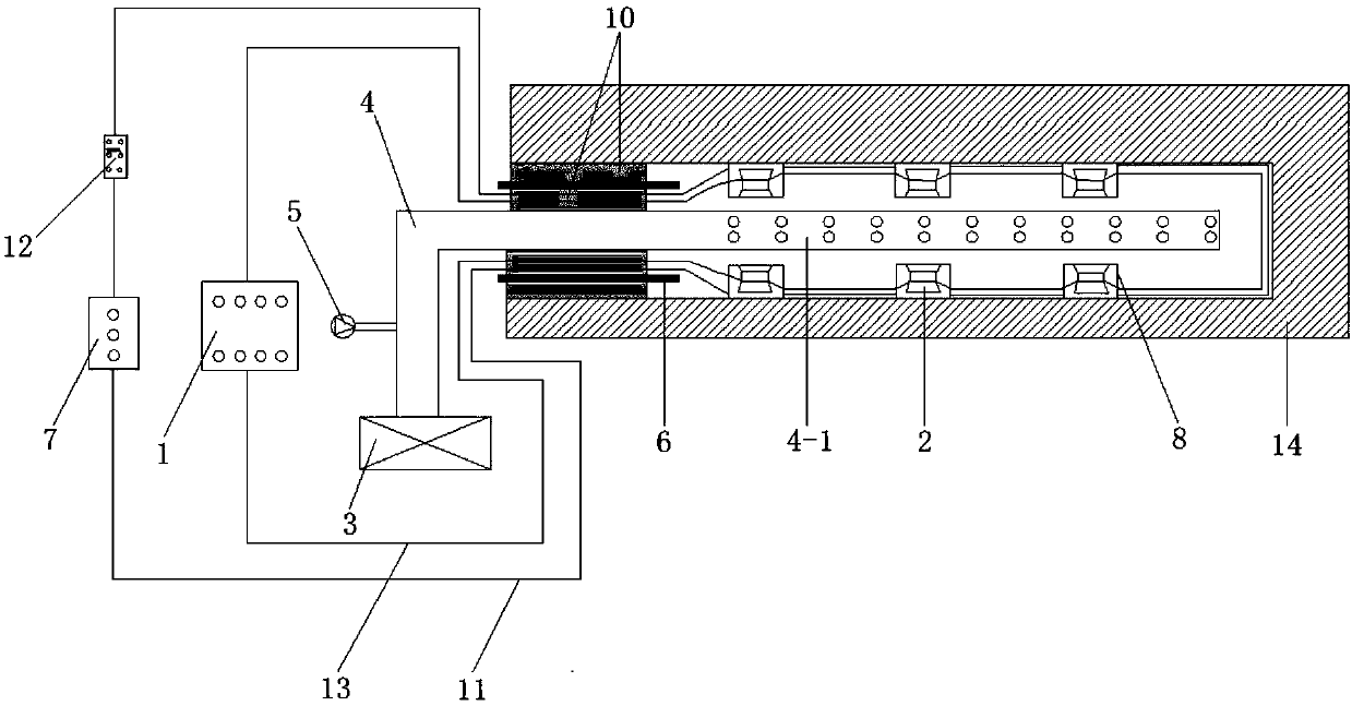
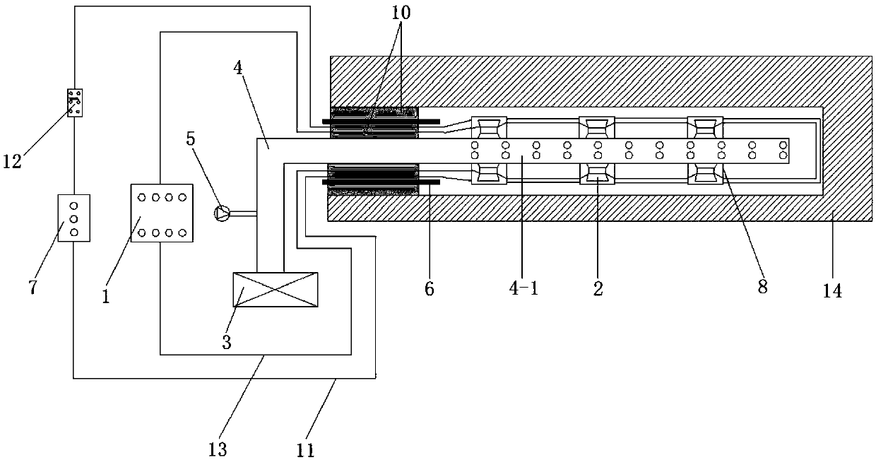
[0034] In this embodiment, the structural diagram of the anti-reflection gas drainage device with frequency conversion vibration in the hole is as follows Figure 1-2 As shown, the figure is a schematic diagram of the working state of 1 gas drainage, figure 2 It is a schematic diagram of the device installed in the borehole.

[0035] The in-hole frequency conversion vibration anti-reflection gas drainage device provided in this embodiment includes a frequency conversion ultrasonic generator 1, 6 ultrasonic transducers 2, a gas drainage pump 3, a gas drainage pipe 4, and a gas flow meter 5, The sealing pipe 6, the electric control box 7, the installation shell 8, the ultrasonic transducer is located in the borehole, and the ultrasonic generator, electric control box, gas extraction pump and gas flow meter are located in the roadway outside the borehole.

[0036] The borehole is located in the coal seam 14 to be treated for gas and is set horizontally. The outer diameter of th...

Embodiment 2

[0045] In this embodiment, the structural diagram of the anti-reflection gas drainage device with frequency conversion vibration in the hole is similar to that shown in Figure 1-2 As shown, the figure is a schematic diagram of the working state of 1 gas drainage, figure 2 It is a schematic diagram of the device installed in the borehole.

[0046] The in-hole frequency conversion vibration anti-reflection gas extraction device provided in this embodiment includes a frequency conversion ultrasonic generator 1, 4 ultrasonic transducers 2, a gas extraction pump 3, a gas extraction pipe 4, and a gas flow meter 5, The sealing pipe 6, the electric control box 7, the installation shell 8, the ultrasonic transducer is located in the borehole, and the ultrasonic generator, electric control box, gas extraction pump and gas flow meter are located in the roadway outside the borehole.

[0047] The borehole is located in the coal seam 14 to be treated for gas. The borehole is set up obliq...

Embodiment 3

[0056] In this embodiment, the structural diagram of the anti-reflection gas drainage device with frequency conversion vibration in the hole is similar to that shown in Figure 1-2 As shown, the figure is a schematic diagram of the working state of 1 gas drainage, figure 2 It is a schematic diagram of the device installed in the borehole.

[0057] The in-hole frequency conversion vibration anti-reflection gas extraction device provided in this embodiment includes a frequency conversion ultrasonic generator 1, 10 ultrasonic transducers 2, a gas extraction pump 3, a gas extraction pipe 4, and a gas flow meter 5, The sealing pipe 6, the electric control box 7, the installation shell 8, the ultrasonic transducer is located in the borehole, and the ultrasonic generator, electric control box, gas extraction pump and gas flow meter are located in the roadway outside the borehole.

[0058] The borehole is located in the coal seam 14 to be treated for gas. The borehole is set oblique...


PUM


Abstract

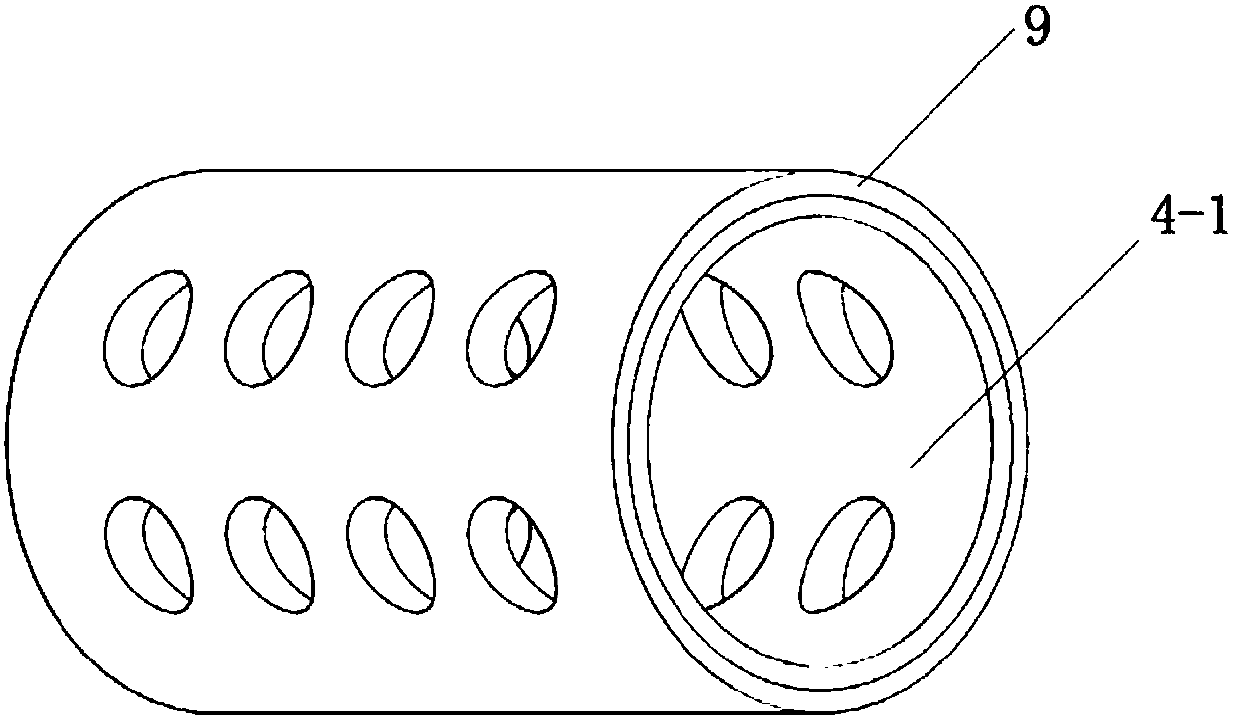
The invention provides a hole interior variable-frequency vibration anti-reflection gas extraction method and device. The hole interior variable-frequency vibration anti-reflection gas extraction device comprises a variable-frequency ultrasonic generator, an ultrasonic transducer, a gas extraction pump, a gas extraction pipe, an electric cabinet and a mounting shell. One end of the gas extractionpipe is connected with the gas extraction pump, and the other end of the gas extraction pipe is provided with a multi-hole section; a magnetic layer is arranged on the outer wall of the multi-hole section, and the mounting shell is provided with an electromagnetic cambered surface matched with the outer wall of the gas extraction pipe in shape; the ultrasonic transducer is fixed in the mounting shell, and after first explosion-proof guide wires are connected in series, the electromagnetic cambered surface is connected with the electric cabinet through a double-point double-throw switch; aftersecond explosion-proof guide wires are connected in series, the ultrasonic transducer is connected with the ultrasonic generator, and the double-point double-throw switch is adjusted to change the current direction so that magnetism of the electromagnetic cambered surface can be changed; and through the attractive or repelling effect between the magnetic layer and the electromagnetic cambered surface, the mounting shell is fixed to the multi-hole section of the gas extraction pipe or the inner wall of a drill hole.

Description

technical field [0001] The invention belongs to the technical field of gas drainage, and relates to a gas drainage method and device for in-hole frequency conversion vibration anti-reflection gas drainage. Background technique [0002] Coal is an important energy source indispensable to human production and life. The development of coal and the safety of coal mines are the most important part of energy security. Coal mine safety production has always been the focus of research and attention. The gas content of coal seams in my country is generally high, and high-outburst mines account for 44% of the total number of mines, and the proportion is as high as 72% in key state-owned coal mines. The occurrence and mining conditions of underground coal seams are complex. As the mining depth continues to increase, coal and gas outbursts are serious and the risk factor is high. Safety accidents caused by gas outbursts are common. Therefore, effective control measures must be taken to...

Claims


Application Information

Patent Timeline
Patent Type & Authority Applications(China)
IPC IPC(8): E21F7/00E21B43/00E21B28/00
CPCE21B28/00E21B43/003E21F7/00
Inventor 高明忠张茹刘强陈海亮鲁义强李安强汪文勇彭高友陆彤
Owner SICHUAN UNIV
Learn More