Display panel and detection method thereof, flexible circuit board and display device

A flexible circuit board and display panel technology, applied in the direction of measuring device, measuring electricity, printed circuit, etc., can solve the problems of easily puncturing the contact pad, judging the binding state, short circuit of the contact pad, etc.

Inactive Publication Date: 2018-02-09
BOE TECH GRP CO LTD +1
View PDF4 Cites 31 Cited by
  • Summary
  • Abstract
  • Description
  • Claims
  • Application Information

AI Technical Summary

Problems solved by technology

However, the bonding process is usually due to improper conditions such as temperature, pressure, and alignment process. After bonding, some or all of the contact electrodes on the display panel and the contact pads on the flexible circuit board will be open, or adjacent contacts will appear. Electrode or adjacent contact pad short circuit
[0004] Usually, some components, such as diodes, can be welded in the component area on the FPC. The FPC with components welded can be expressed as FPCA (Flexible Printed Circuit Assembly). After binding the display panel and the flexible circuit board, for components with components The flexible circuit board (FPCA) of the device cannot judge the binding state by testing the channel resistance. Even a simple FPC without components needs to use a multimeter to tie the contact pads (also called golden fingers) on the flexible circuit board. To judge the binding effect, this way of detecting the binding effect is very easy to puncture the contact pad

Method used


Image

  • Display panel and detection method thereof, flexible circuit board and display device
  • Display panel and detection method thereof, flexible circuit board and display device
  • Display panel and detection method thereof, flexible circuit board and display device

Examples


Embodiment Construction

[0067] In view of the problem that the binding effect cannot be effectively detected in the prior art, embodiments of the present invention provide a display panel, a detection method thereof, a flexible circuit board, and a display device.

[0068] The specific implementations of the display panel, the detection method, the flexible circuit board, and the display device provided by the embodiments of the present invention will be described in detail below with reference to the accompanying drawings. The size and shape of each part in the drawings do not reflect the true proportions, and the purpose is only to illustrate the content of the present invention.

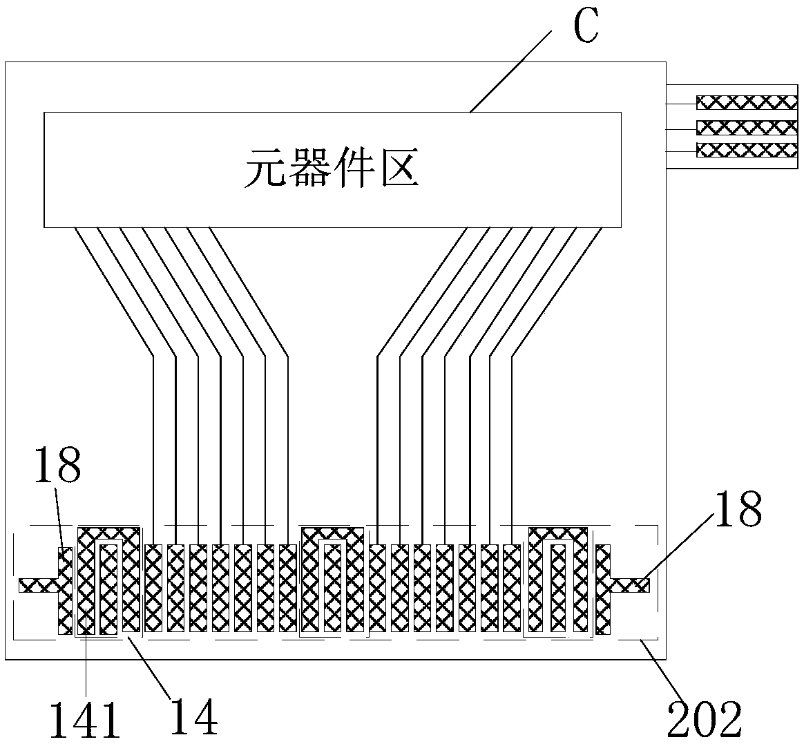
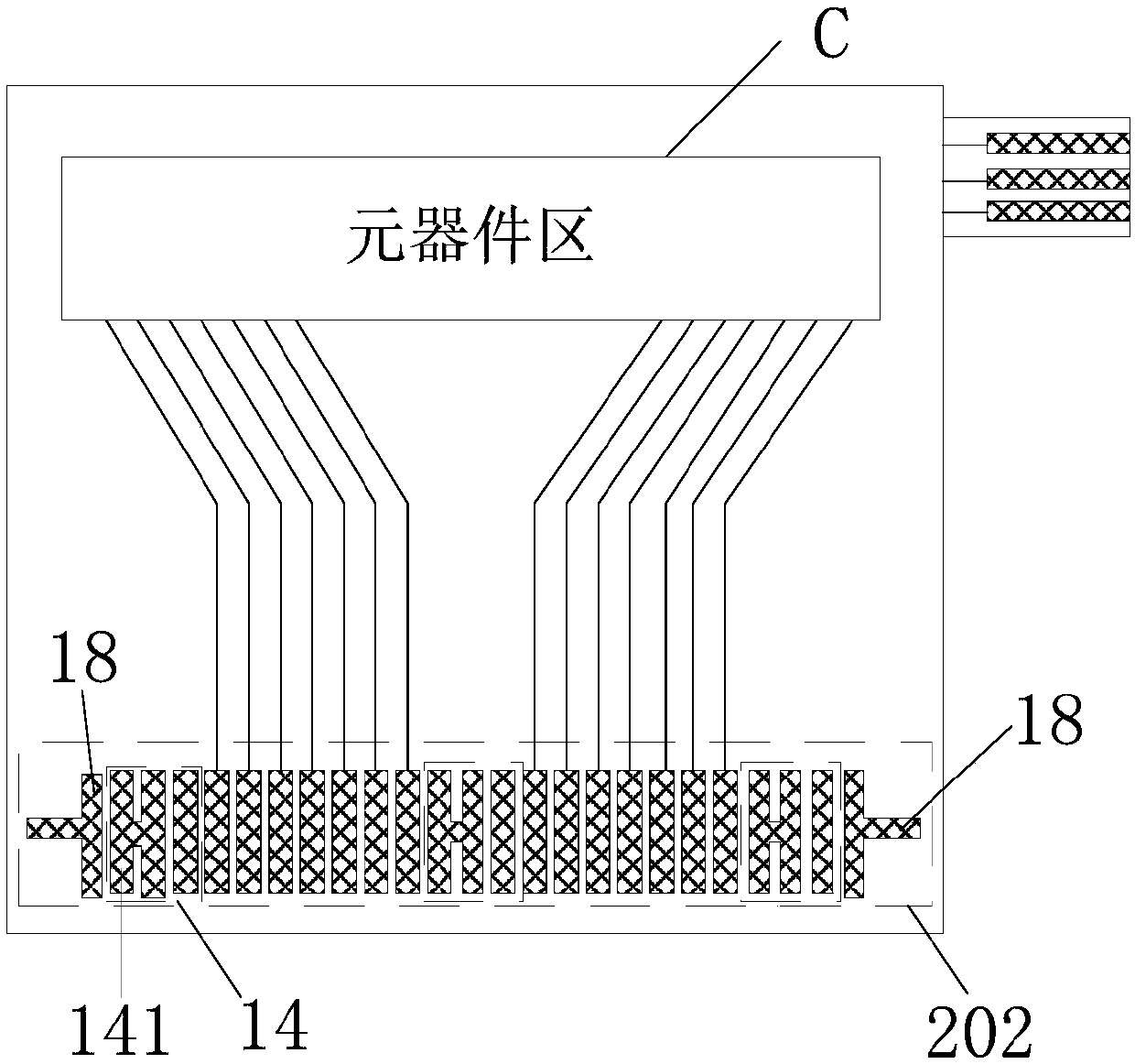
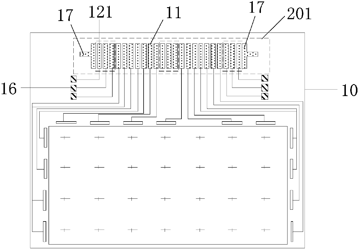
[0069] In the embodiment of the present invention, figure 1 with figure 2 Respectively are schematic diagrams of the structure of flexible circuit boards applied to display panels, image 3 For and figure 1 or figure 2 The shown schematic diagram of the structure of the display panel corresponding to the flexible circuit boa...


PUM


Abstract

The invention discloses a display panel and a detection method thereof, a flexible circuit board and a display device. A second binding area in the flexible circuit board comprises a plurality of contact pads and at least one test pad group, wherein the plurality of contact pads are used for being bound to a plurality of corresponding contact electrodes in a first binding area; each test pad groupis used for being bound to a corresponding test electrode group in the first binding area and comprises a plurality of test pads; the test pads are used for being bound to corresponding test electrodes; and the test pad groups are also used for judging the binding state of the plurality of contact pads and the plurality of contact electrodes through detecting the on-off states between the test pads and the corresponding test electrodes after the first binding area is bound to the second binding area. According to the flexible circuit board disclosed by the embodiment of the invention, the binding effect can be effectively and quickly detected through arranging the test pad groups in the second binding area and binding the flexible circuit board and the display panel.

Description

Technical field [0001] The invention relates to the field of display technology, in particular to a display panel, a detection method thereof, a flexible circuit board and a display device. Background technique [0002] With the continuous development of display technology, display screens or touch screens have been widely used in people’s lives. Among them, liquid crystal displays (LCD) have the characteristics of small size, low power consumption, and no radiation. Organic electroluminescent devices (Organic Light-Emitting Diode, OLED) has the advantages of self-luminescence, fast response, wide viewing angle, high brightness, bright colors, thin and light. [0003] In the prior art, the bonding area of ​​the display panel includes a plurality of contact electrodes (pads), and the bonding area on the flexible circuit board includes a plurality of contact pads (pins). The bonding process of the display screen or the touch screen, Generally, it is necessary to bind the contact pad...

Claims


Application Information

Patent Timeline
Patent Type & Authority Applications(China)
IPC IPC(8): H05K1/11H05K1/02G09G3/00G09F9/00G02F1/1345
CPCG02F1/13452G09F9/00G09G3/006H05K1/0268H05K1/111H05K1/118H05K2203/163H05K3/361H05K2201/09781H05K2201/09918G01R31/2818G01R31/2812G02F1/13456G02F1/136254H05K1/189G01R31/2825G02F1/133305
Inventor 赵雪梅李虎何剑张志
Owner BOE TECH GRP CO LTD
Why Eureka
Try Eureka