
Lubricating device used for wheel machining

A lubricating device, wheel machine technology, applied in metal processing equipment, metal processing machine parts, manufacturing tools, etc., can solve the problems of operator health injury, high cost of cutting fluid use, odor and odor, etc., to achieve convenient and economical operation. The effect of manufacturing cost and simple structure

Inactive Publication Date: 2018-02-13
CITIC DICASTAL
View PDF14 Cites 2 Cited by
  • Summary
  • Abstract
  • Description
  • Claims
  • Application Information

AI Technical Summary

Problems solved by technology

[0002] At present, when machining aluminum wheels, the lubrication method is cutting fluid lubrication, that is, the cutting fluid with a suitable concentration is prepared in advance, and a large amount of cutting fluid is sprayed to the processing part by the liquid supply device for lubrication, and then the waste fluid is recovered. There are many disadvantages in the traditional cutting fluid lubrication method. The use cost of cutting fluid is very high. During the use, there are cutting fluid running, popping, dripping and leaking, which is easy to produce peculiar smell and smell, which will not only pollute the environment, but also affect the safety of operators Health causes certain harm. Therefore, for the aluminum wheel machining process, it is necessary to seek a new, green and environmentally friendly lubrication method to replace the traditional cutting fluid lubrication, so as to reduce production costs and improve the production environment.
Minimal quantity lubrication cutting processing technology is to mix a small amount of pollution-free oil mist into the compressed gas to replace a large amount of cutting fluid to cool and lubricate the cutting point, and spray high-speed oil mist to increase the permeability of the lubricant and improve the cooling and lubrication effect. In order to improve the surface processing quality of the workpiece, it is currently widely used in the fields of gear, crankshaft, mold processing, etc., but it has never been involved in the aluminum wheel processing industry. Based on this situation, this patent innovatively introduces the micro-quantity lubrication technology into the aluminum wheel manufacturing industry. Invention A minimal quantity lubrication device for wheel machining

Method used


Image

  • Lubricating device used for wheel machining
  • Lubricating device used for wheel machining

Examples


Embodiment Construction

[0011] The details and working conditions of the specific device proposed by the present invention will be given below in conjunction with the description of the accompanying drawings.

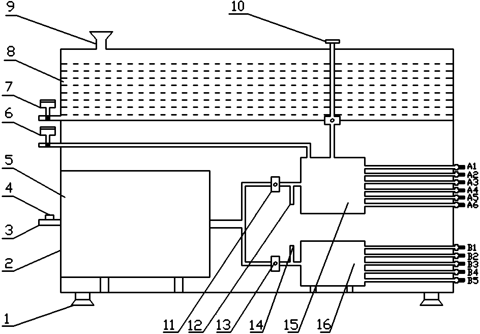
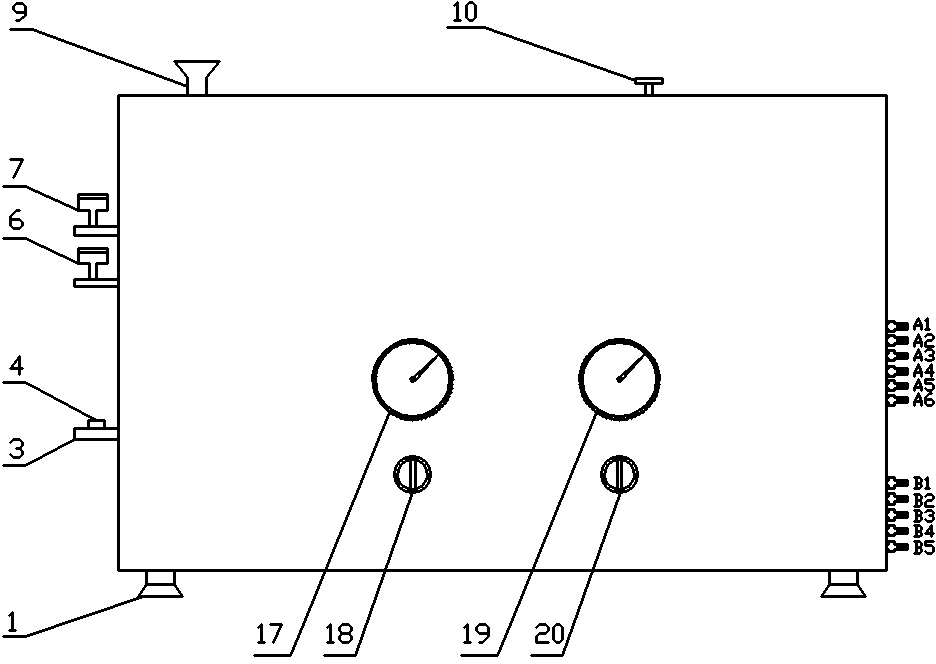
[0012] A lubricating device for wheel machining, which consists of an adjustable foot 1, a frame 2, a power interface 3, a power switch 4, an air compressor 5, a safety valve 6, an oil drain valve 7, an oil tank 8, an oil filling port 9, and an oil volume adjustment Valve 10, oil mist pressure regulating valve 11, oil mist pressure gauge interface 12, air pressure regulating valve 13, air pressure gauge interface 14, oil mist generator 15, air divider 16, oil mist pressure gauge 17, oil mist pressure adjustment Knob 18, compressed air pressure gauge 19, air pressure adjustment knob 20, A1-A6 oil mist output interface and B1-B5 compressed air output interface. The air compressor 5 is fixed on the frame 2, and its output end is divided into two circuits, one is connected to the oil mist pressure...


PUM


Abstract

The invention provides a lubricating device used for wheel machining. The lubricating device used for wheel machining is composed of an air compressor, a safety valve, an oil drain valve, an oil tank,an oil filling port, an oil quantity regulation valve, an oil mist pressure regulation valve and the like. The air compressor is fixed to a rack. The output end of the air compressor is divided intotwo paths, one path is connected with the oil mist pressure regulation valve, and the oil mist pressure regulation valve is externally connected with an oil mist pressure regulation knob; and the other path is connected with an air pressure regulation valve, and the air pressure regulation valve is externally connected with an air pressure regulation knob. An oil mist pressure gauge connector is arranged between the oil mist pressure regulation valve and an oil mist generator and externally connected with an oil mist pressure gauge. An air pressure gauge connector is arranged between the air pressure regulation valve and an air separator and externally connected with a compressed air pressure gauge. According to the lubricating device used for wheel machining, the lubrication technologicalrequirements of wheel machining can be met, a traditional lubricating method based on cutting fluid can be completely replaced by the lubricating device, the manufacturing cost is greatly reduced, and the manufacturing environment is improved; and the lubricating device has the characteristics of being simple in structure, easy to manufacture, convenient and fast to operate and the like.

Description

technical field [0001] The invention relates to the technical field of wheel hub machining, in particular to a lubricating device for wheel machining. Background technique [0002] At present, when machining aluminum wheels, the lubrication method is cutting fluid lubrication, that is, the cutting fluid with a suitable concentration is prepared in advance, and a large amount of cutting fluid is sprayed to the processing part by the liquid supply device for lubrication, and then the waste fluid is recovered. There are many disadvantages in the traditional cutting fluid lubrication method. The use cost of cutting fluid is very high. During the use, there are cutting fluid running, popping, dripping and leaking, which is easy to produce peculiar smell and smell, which will not only pollute the environment, but also affect the safety of operators Health causes certain harm. Therefore, for the aluminum wheel machining process, it is necessary to seek a new, green and environmen...

Claims


Application Information

Patent Timeline
Patent Type & Authority Applications(China)
IPC IPC(8): B23Q11/10
CPCB23Q11/10B23Q11/005B23Q11/1046Y02P70/10
Inventor 刘会莹薛博文
Owner CITIC DICASTAL
Learn More