optical display device

A technology of diffractive optical elements and gratings, which is applied in the field of augmented reality optical display devices, and can solve problems such as difficult application of coating layers

Active Publication Date: 2020-05-08
WAVE OPTICS
View PDF4 Cites 1 Cited by
  • Summary
  • Abstract
  • Description
  • Claims
  • Application Information

AI Technical Summary

Problems solved by technology

A possible disadvantage of this technique is the additional production cost associated with the dielectric layer
Additionally, the sloped surface of the grating can make it difficult to apply a uniform coating across the entire length of the blaze

Method used


Image

  • optical display device
  • optical display device
  • optical display device

Examples


Embodiment Construction

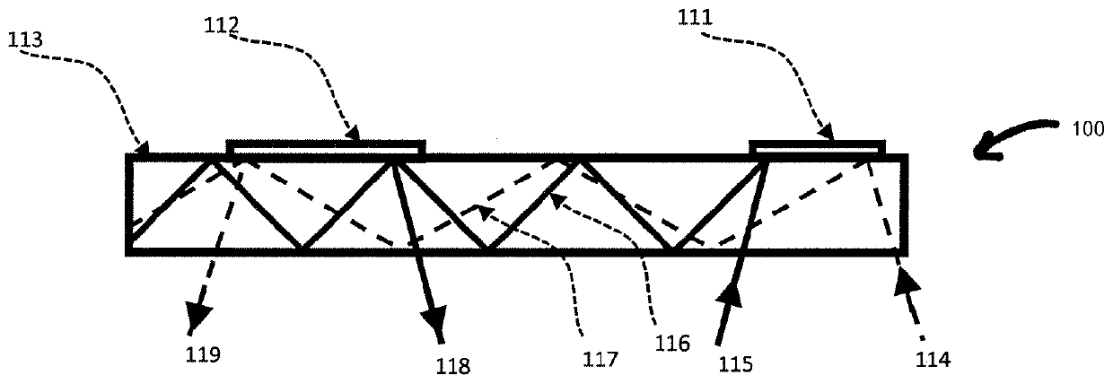
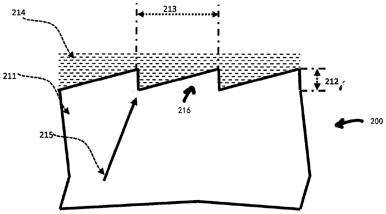
[0039] Figure 6 It is a cross-sectional view of the optical display device 600 in the embodiment of the present invention. The display device 600 includes an input diffractive optical element 618 mounted on a substrate 611 . The input diffractive optical element 618 comprises a blazed grating 619 with a period 613 of 520 nm and a feature height 612 of 220 nm. The input diffractive optical element 618 also includes a residual layer 617 formed from the same polymer-based material that forms the blazed grating 619 and produced simultaneously with the blazed grating 619 . Residual layer 617 is positioned adjacent to substrate 611 . The depth of the residual layer 617 is consistent across the blazed grating 619 . In this example, the residual layer depth is 80nm. On the surface of the blazed grating 619 a silver coating 614 is applied. The substrate 611 is generally made of glass and has a refractive index of 1.5. The refractive index of the input diffractive optical element...


PUM

PropertyMeasurementUnit
angle of incidenceaaaaaaaaaa
thicknessaaaaaaaaaa
thicknessaaaaaaaaaa

Abstract

An optical display device (600, 700) is disclosed. A diffractive optical element (618, 718) is mounted on the substrate (611, 711). The diffractive optical element comprises a blazed grating (619, 719) and a residual layer (617, 717) formed of the same polymer-based material from which the blazed grating was formed. The residual layer (617, 717) is positioned adjacent to the substrate (611, 711) and provides a refractive index mismatch therebetween. The depth of the residual layer is selected such that, for a selected angle of incidence, light diffracted by the grating and light reflected by the interface recombine and interfere constructively to undergo thin-film interference.

Description

technical field [0001] The present invention relates to augmented reality optical display devices, which can be used in applications such as heads-up displays, augmented reality glasses or head-mounted displays. In particular, the present invention relates to devices capable of improving the uniformity of illumination of a display over a wide field of view. Background technique [0002] Augmented reality displays allow users to view their surroundings as well as projected images. In military or transportation applications, projected images can be superimposed on the real world perceived by the user. Other applications for these displays include video games and wearable devices such as glasses. [0003] In a normal setup, a transparent display is placed in front of the user so they can continue to see the physical world. The display screen is usually a glass waveguide with a projector on one side. Light from the projector is coupled into the waveguide by an input diffract...

Claims


Application Information

Patent Timeline
Patent Type & Authority Patents(China)
IPC IPC(8): G02B27/01G02B27/10G02B5/18G02B6/34
CPCG02B5/1814G02B6/34G02B27/0101G02B27/0172G02B27/1086G02B2027/0118G02B2027/0123G02B6/00G02B6/0013G02B6/0033G02B2027/0116
Inventor 萨利姆·瓦莱拉
Owner WAVE OPTICS
Why Eureka
Try Eureka