Mold modification mechanism for modifying bending deformation of punch products

A bending deformation and vertical bending deformation technology, applied in the direction of forming tools, manufacturing tools, metal processing equipment, etc., can solve the problems of stamping forming, low production cost, bending deformation of metal lead frames, etc., to avoid the cumbersome maintenance and adjustment. Action, improve the production qualification rate, and facilitate the adjustment of the work effect

Inactive Publication Date: 2018-02-16
ZHONGSHAN FUSHENG ELECTROMECHANICAL
View PDF6 Cites 1 Cited by
  • Summary
  • Abstract
  • Description
  • Claims
  • Application Information

AI Technical Summary

Problems solved by technology

Although corrosion processing can achieve very fine precision, it cannot achieve high production efficiency and low production cost. With the rapid decline in the price of IC chips represented by computer memory sticks and CPUs, stamping and forming IC chip metal lead frames are used. It is an important way to reduce the price of IC chips and improve production efficiency
[0003] However, after the metal lead frame of the IC chip is stamped and produced, it is easy to cause bending deformation of the metal lead frame due to the existence of internal stress. For example, the arc bending deformation along the vertical downward direction of the IC chip metal lead frame will seriously affect the IC chip. The subsequent manufacturing process of the chip is carried out smoothly, so the problem of bending and deformation of the metal lead frame of the IC chip is a technical problem that plagues stamping and forming, which cannot meet the increasingly tense demand, and also restricts the further development of information technology.

Method used


Image

  • Mold modification mechanism for modifying bending deformation of punch products
  • Mold modification mechanism for modifying bending deformation of punch products
  • Mold modification mechanism for modifying bending deformation of punch products

Examples


Embodiment Construction

[0041] The application will be further described in detail below through specific implementations in conjunction with the drawings.

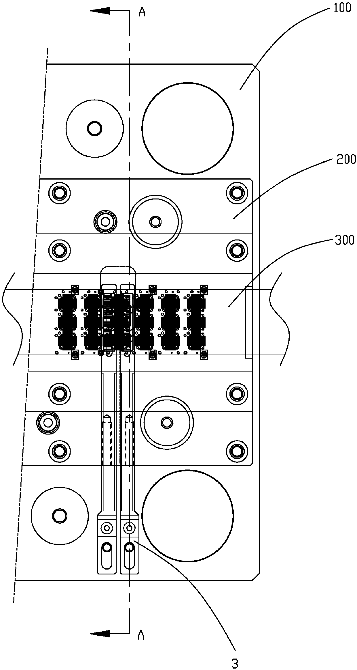
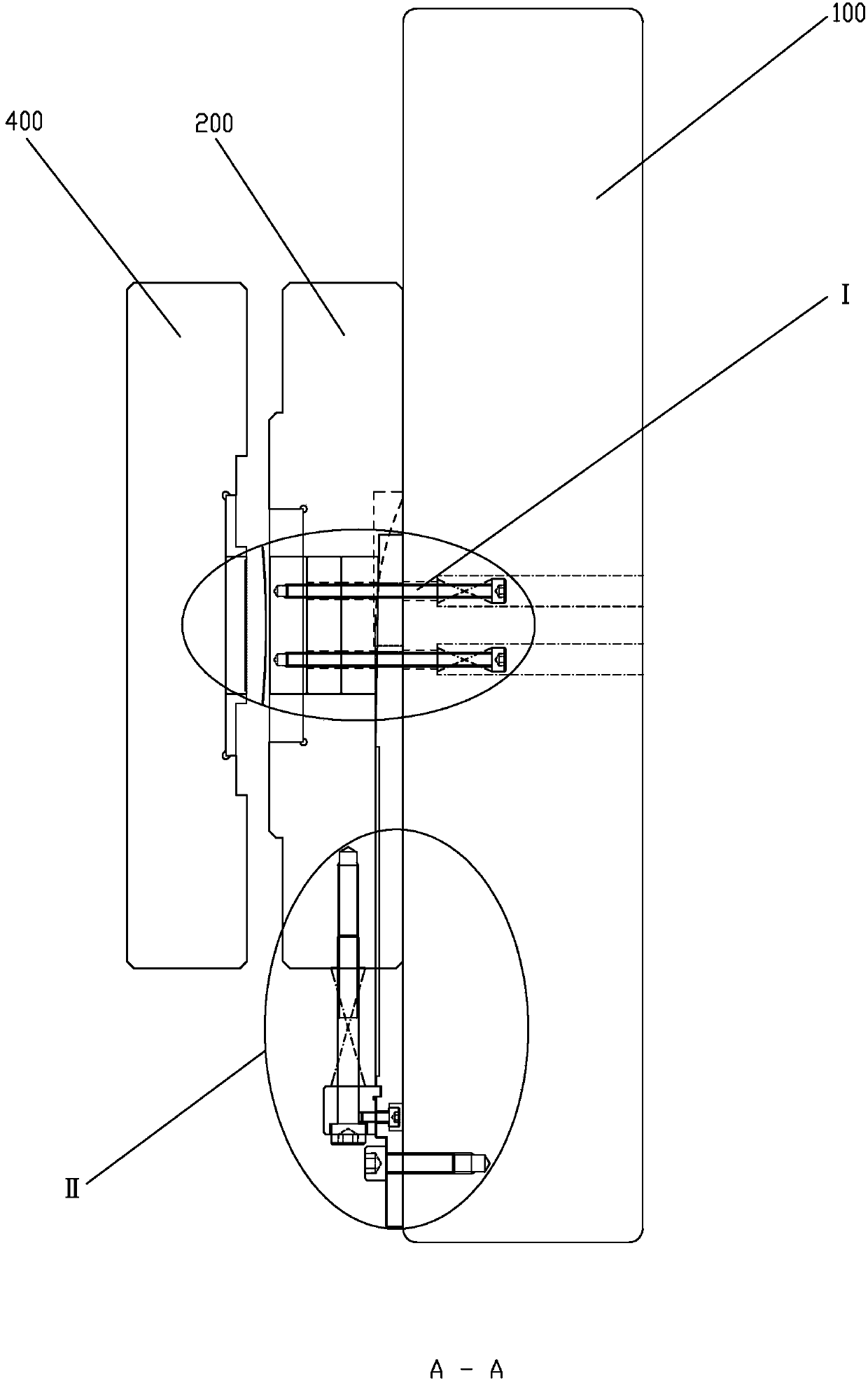
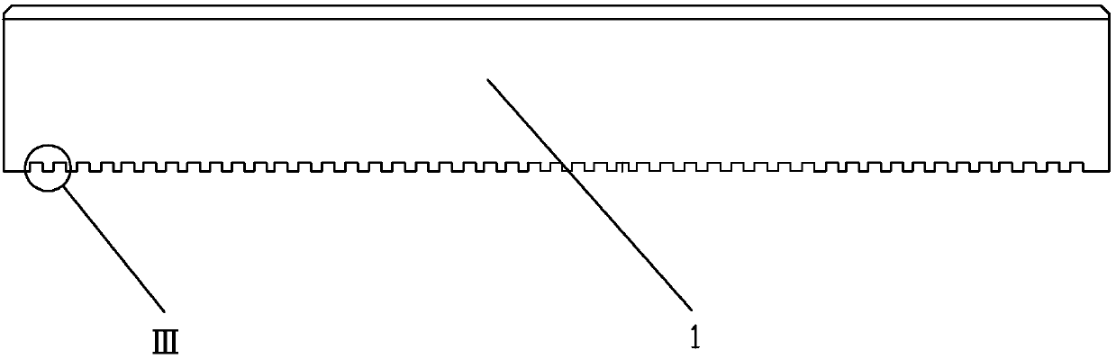
[0042] Such as Figure 1-12 As shown, the mold correction mechanism for correcting the bending deformation of the stamping product includes a stripping correction insert 1, a lower mold correction insert 2 and a movement adjustment assembly 3.

[0043] Specifically, the stripping correction insert 1 is arranged on the stripping back plate 400, above the product strip 300 that has vertical bending deformation and moves forward in the transverse direction of the stripping back plate 400, and is provided on its lower side There are a plurality of modified tooth grooves 11 which are concave and are arranged at intervals along the longitudinal direction. The lower mold correcting insert 2 is arranged on the lower mold back plate 200, located below the stripping correcting insert 1, and on its upper side is provided with the correcting tooth groove 11 to ...


PUM


Abstract

The invention discloses a mold modification mechanism for modifying bending deformation of punch products. The mold modification mechanism comprises a stripper modification insert arranged on a stripper backboard and a lower mold modification insert arranged on a lower mold backboard and is located under the stripper modification insert, multiple indents and modification tooth grooves distributedalong the longitudinal direction at intervals are arranged in the lower side of the stripper modification insert, and modification convex teeth matched with the modification tooth grooves to modify vertical bending deformation of product material straps. Through vertical matching of the modification tooth grooves and the modification convex teeth, multiple modification positions are formed along the longitudinal direction of the product material straps, an IC (integrated circuit) chip metal lead frame with vertical downward curved bending deformation can be modified, quality requirements can be greatly improved, quality requirements of the whole production process of an IC chip are favorably stabilized, production qualified rate can be greatly increased, increasing tense requirements are met, and further development of information technology is favorably promoted.

Description

【Technical Field】 [0001] The application relates to the technical field of mold structures, and specifically to a mold correction mechanism for correcting bending deformation of stamping products. 【Background technique】 [0002] With the development of information technology, there is an increasing demand for metal lead frames in integrated circuit (IC) chips, and their shapes are becoming more minute and precise. There are two production methods for IC chip lead frames: corrosion processing and stamping processing. Although corrosion processing can achieve very fine precision, it cannot achieve higher production efficiency and lower production costs. With the rapid decline in the price of IC chips represented by computer memory and CPU, stamping and forming IC chip metal lead frames are used It is an important way to reduce IC chip prices and improve production efficiency. [0003] However, after the stamping and production of the IC chip metal lead frame is completed, the metal...

Claims


Application Information

Patent Timeline
Patent Type & Authority Applications(China)
IPC IPC(8): B21D37/10
CPCB21D37/10
Inventor 邵玉花夏世新刘榕李勇何华杰
Owner ZHONGSHAN FUSHENG ELECTROMECHANICAL
Why Eureka
Try Eureka