Construction method of profile steel and mixing-jetted cement soil curtain support pile

A construction method and a technology for supporting piles, which are applied in excavation, sheet pile walls, foundation structure engineering, etc., can solve problems that are not involved, cannot reach the design depth, and cannot do what they want, so as to reduce disturbance and damage, improve the occlusal effect, easy chiseling effect

Inactive Publication Date: 2018-02-16
北京建材地质工程有限公司 +2
View PDF3 Cites 3 Cited by
  • Summary
  • Abstract
  • Description
  • Claims
  • Application Information

AI Technical Summary

Problems solved by technology

However, this method is mainly suitable for soft strata dominated by clay and silty sand, but it is not suitable for construction in hard soil strata in the northern region, especially in sand stratum and sand pebble stratum, and it cannot reach the design depth, so it is no longer applicable
For example, so far, there is only one case of using a three-axis mixer to construct a cement-soil diaphragm wall in Beijing, and it does not involve the sandy pebble formation in Beijing.

Method used


Image

  • Construction method of profile steel and mixing-jetted cement soil curtain support pile
  • Construction method of profile steel and mixing-jetted cement soil curtain support pile

Examples


Embodiment 1

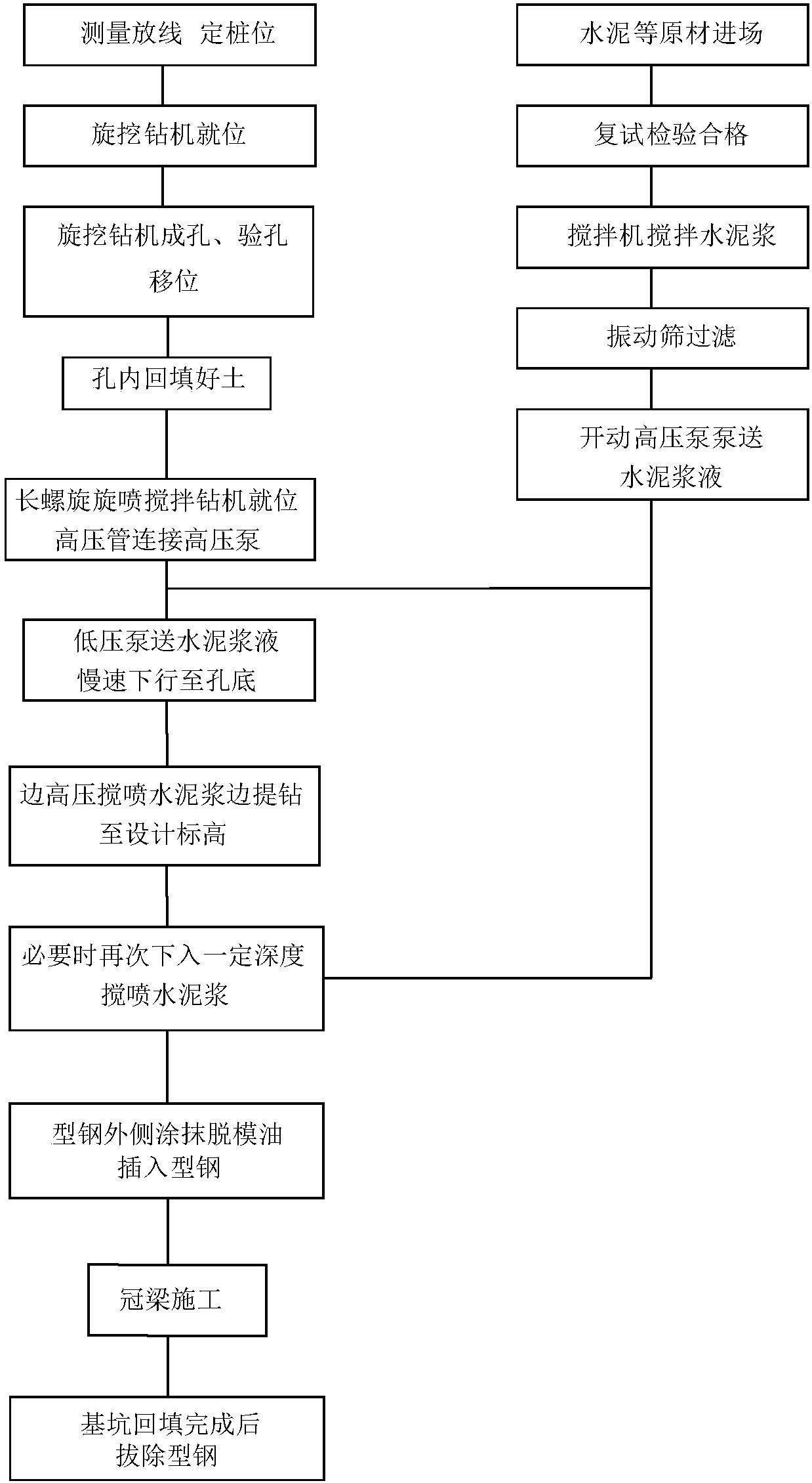
[0042] like figure 2 Shown, a kind of construction method of section steel mixing and spraying cement-soil curtain curtain support pile, comprises the following construction steps:

[0043] Step a, measurement and setting out: measure and set out on a flat site, insert wooden sticks or steel bar sticks at the released pile positions for identification; in addition, make leading piles next to the pile positions so that they can be reviewed at any time when there is a deviation in the pile positions; leading piles It is two identification piles that form a straight line with the center of the pile position. The usual method for leading piles is to drill a deep hole on the ground with a steel drill or a hole puncher, and pour white lime powder into it;

[0044] Step b, the rotary drilling rig is in place: the operator controls the movement of the drilling rig according to the released pile position to ensure that the drilling axis is in place, and uses the self-contained device ...

Embodiment 2

[0054] The difference from Embodiment 1 is that in step i, when the ground space is narrow and the special lifting machine has no operating space, the section steel is pre-lifted with a jack, and after reaching a certain height, such as after pulling out 1m, use a tower crane or The crane pulls up the whole section steel for recycling.

[0055] In addition, in order to further improve the reliability of the water-stop curtain, after the construction of the support piles is completed, with the excavation of the foundation pit, detachable anchor rods are implemented layer by layer on the inner wall of the foundation pit, and the net is hung with shotcrete. When the foundation construction is completed and the backfilling of the fertilizer tank of the foundation pit reaches the height of the anchor bolts, the anchor bolts are removed layer by layer for recycling.


PUM


Abstract

The invention discloses a construction method of a profile steel and mixing-jetted cement soil curtain support pile. According to key points of the technical scheme, the construction method comprisesthe following construction steps that survey and setting out are performed; a rotary drilling rig is arranged in place; drilling is performed; holes are filled with soil, and slurry is mixed outside the holes; a long auger rotary-jetting stirring drilling jig is arranged in place; cement soil pile mixing-jetting construction is performed; profile steel is inserted into piles; top beam constructionis performed; and the profile steel is pulled out. The method is applicable to construction on hard pan and gravel layers; the support pile after construction is completed achieves the combined effect of water stopping and supporting, and the inserted profile steel can be recycled, so that sources are saved, and the environment is protected; and the mixing-jetted support pile is independent of undisturbed soil, and is good in pile forming quality.

Description

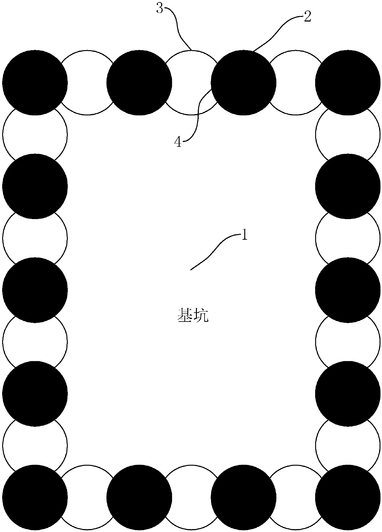
technical field [0001] The invention relates to the field of water-stop curtain engineering for foundation pits, in particular to a construction method for steel-sprayed cement-soil curtain curtain support piles. Background technique [0002] like figure 1 As shown, the water-stop curtain refers to a continuous water-stop body arranged on the periphery of the building foundation pit 1 to ensure the excavation of the foundation pit 1 and to prevent or reduce the flow of groundwater at the side wall of the foundation pit and at the bottom of the foundation pit. The commonly used structure of the water-stop curtain is that the support piles 2 and the water-stop piles 3 are arranged at intervals in a row, and partially overlap each other to form a joint 4 . The support pile 2 mainly plays the role of retaining soil, and the water stop pile 3 plays the role of blocking the water layer outside the foundation pit from flowing into the foundation pit. [0003] The water stop pile ...

Claims


Application Information

Patent Timeline
IPC IPC(8): E02D19/12E02D17/04E02D5/46
CPCE02D19/12E02D5/46E02D17/04
Inventor 何世鸣刘军周与诚李江张明中陈辉关龙巫冬妹贾城李长生梁成华司呈庆王建明郁河坤黄鑫峰刘志刚洪伟陈鹏
Owner 北京建材地质工程有限公司
Why Eureka
Try Eureka