Flame recognition system for aeroengine combustor

A technology for aero-engine and flame recognition, which is applied in the field of flame recognition system of aero-engine combustors, can solve problems such as slow speed and inaccurate results, and achieve the effects of fast speed, expanded application fields, and high accuracy

Active Publication Date: 2019-07-26
AECC HUNAN AVIATION POWERPLANT RES INST
View PDF5 Cites 1 Cited by
  • Summary
  • Abstract
  • Description
  • Claims
  • Application Information

AI Technical Summary

Problems solved by technology

[0004] The invention provides a flame identification system for the combustion chamber of an aero-engine to solve the technical problems of slow speed and inaccurate results of traditional measuring devices and methods

Method used


Image

  • Flame recognition system for aeroengine combustor
  • Flame recognition system for aeroengine combustor
  • Flame recognition system for aeroengine combustor

Examples


Embodiment Construction

[0024] It should be noted that, in the case of no conflict, the embodiments in the present application and the features in the embodiments can be combined with each other. The present invention will be described in detail below with reference to the accompanying drawings and examples.

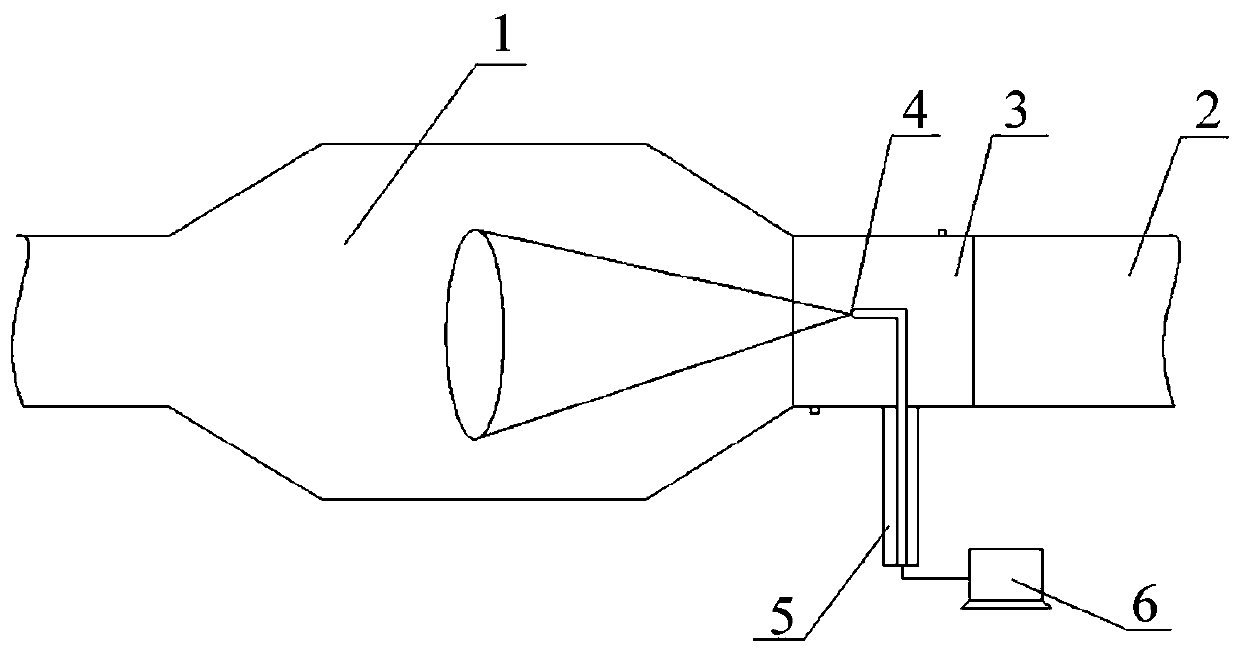
[0025] refer to figure 1 , the preferred embodiment of the present invention provides a flame identification system for aero-engine combustors, which is mainly applied to ignition / flame-out tests of single-pipe / single-head or full-ring combustors. Preferably, the combustor 1 is a single tube combustor or a full ring combustor structure.

[0026] The present invention is used for the flame recognition system of aeroengine combustor, comprises combustion chamber 1 and exhaust section 2, is connected with the flame observation transfer section 3 that communicates with both between combustion chamber 1 and exhaust section 2, and flame observation transfer section A high-temperature refraction len...


PUM


Abstract

The invention discloses a flame recognition system used for an aircraft engine combustor. The flame recognition system used for the aircraft engine combustor comprises a combustor body and an exhausting segment; a flame observing turning-connection segment communicated with the combustor body and the exhausting segment is connected between the combustor body and the exhausting segment; a high temperature refracting mirror with the light incoming end right opposite to the combustor body is installed in the flame observing turning-connection segment; the light outgoing end of the high temperature refracting mirror is connected with a flame image shooting system located outside the flame observing turning-connection segment; the flame image shooting system is connected with a flame image processing system and recognizing system; the flame image shooting system is used for acquiring a real-time image of the combustor body through the high temperature refracting mirror; and the flame imageprocessing system and recognizing system is used for performing real-time diagnosis on the state in the combustor body according to the real-time image. According to the lame recognition system used for the aircraft engine combustor, the state of the combustor body is diagnosed in a non-contact manner, speed is high, and the accuracy rate is high; no interference on a flow field is caused, and themeasurement result is not affected by the environment in the combustor body; and the defects of judging on igniting / flameout of a thermocouple in the combustor body are overcome.

Description

technical field [0001] The invention relates to the technical field of flame testing of an aero-engine combustion chamber, in particular to a flame identification system for an aero-engine combustion chamber. Background technique [0002] The combustion chamber is an important part of the aviation propulsion system. The development of propulsion technology depends on the progress of the research on the combustion mechanism. Whether the ignition is successful or not is the first step in the research of the combustion chamber. The traditional measurement point / flame extinguishing is mainly through the layout of three thermocouples at the outlet of the combustion chamber, and the combustion test data of whether the combustion is ignited or not is obtained through contact measurement methods such as the temperature rise method of the thermocouples. Although the traditional contact temperature measurement technology has been developed relatively mature and has high measurement ac...

Claims


Application Information

Patent Timeline
Patent Type & Authority Patents(China)
IPC IPC(8): F23M11/04
CPCF23M11/045
Inventor 陈苗苗袁汀张险蒋荣伟
Owner AECC HUNAN AVIATION POWERPLANT RES INST
Why Eureka
Try Eureka