Microseism positioning and tomographic imaging method

A tomographic imaging and microseismic technology, applied in seismology, seismic signal processing, geophysical measurement, etc., can solve the problems of real result error and time-consuming calculation, and achieve the goal of improving accuracy, reducing number, and reducing dependence Effect

Active Publication Date: 2018-02-16
成都博赫科技有限公司
View PDF2 Cites 6 Cited by
  • Summary
  • Abstract
  • Description
  • Claims
  • Application Information

AI Technical Summary

Problems solved by technology

Because of this, even if the ordinary tomographic equation, the source double-difference tomographic equation and the receiver double-difference tomographic equation are combined, the inversion results are somewhat different from the traditional double-difference tomographic equation without inversion of the microseismic occurrence time. improved, but there is still a large error with the

Method used


Image

  • Microseism positioning and tomographic imaging method
  • Microseism positioning and tomographic imaging method
  • Microseism positioning and tomographic imaging method

Examples


Embodiment 1

[0083] Embodiment 1 is the calculation example of a kind of microseismic positioning and tomographic imaging method proposed by the present invention, and its specific calculation results are further disclosed as follows:

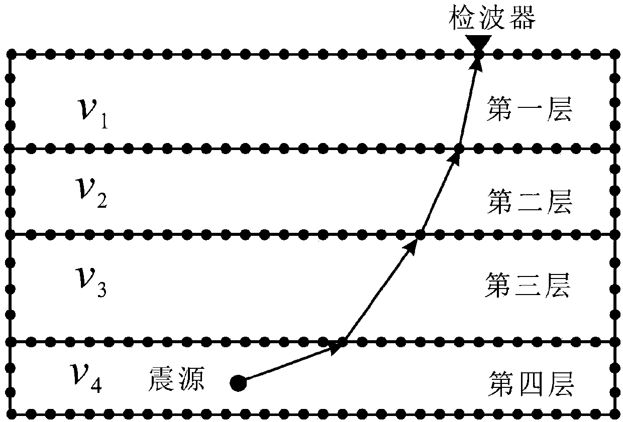
[0084] Such as Figure 4 As shown, the model established for Embodiment 1 of the present invention is a four-layer horizontal layered medium, and the speed is 2.0km / s, 2.4km / s, 2.8km / s and 3.2km / s from the surface downwards, and the layer The depths of the interface are 16m, 30m and 40m respectively. The surface “m” type commonly used in microseismic and the joint observation method in the well are adopted (the geophones are arranged as follows Figure 4 shown in the middle triangle). Figure 4 The dots in the middle represent the set four microseismic events, and their spatial coordinates are S1 (20, 40, 42), S2 (100, 100, 45), S3 (150, 180, 48), S4 (170, 30, 26), The excitation times were 10ms, 15ms, 20ms and 5ms, respectively.

[0085] Figure 5 is ...


PUM


Abstract

A microseism positioning and tomographic imaging method of the present invention comprises a step 1 of reading an initial model and an inversion parameter; a step 2 of adopting an interface element-based shortest path algorithm to calculate the theoretical travel time and a ray path of a microseism event; a step 3 of calculating a first-order partial derivative about a to-be-inverted parameter when an underground medium structure and a microseism event parameter are inverted simultaneously; a step 4 of constructing a tomography equation set that the underground medium structure and the microseism event parameter are inverted simultaneously; a step 5 of solving the tomography equation set via a conjugate gradient method to obtain the updating quantity of the microseism source parameters andthe speed structures; a step 6 of updating and restraining the speed structure models and the microseism source parameters; a step 7 of determining the iteration ending. According to the present invention, aiming at the horizontal layered mediums, and by utilizing the ground and borehole observation travel time data, the speed structure models and the microseism source parameters can be invertedsimultaneously, wherein the microseism source parameters are the microseism source positions and the microseism moments, and the speed structure models are the layer speeds and the layer interface positions.

Description

technical field [0001] The invention belongs to the technical field of microseismic monitoring, in particular to a microseismic positioning and tomographic imaging method. Background technique [0002] Hydraulic fracturing technology is one of the important production stimulation measures in the development process of unconventional oil and gas resources, such as tight sandstone gas, shale gas and coalbed methane. This technology uses the characteristics of fluid pressure transmission to inject fluid at high pressure through hydraulic fracturing and other mining methods. Formation, to break the rock to increase the permeability of the formation, so as to achieve the purpose of increasing production. Microseismic monitoring technology monitors production activities and underground conditions by observing, locating and analyzing microseismic events; this technology can be used for hydraulic fracturing analysis and plays an important role in reservoir development monitoring. H...

Claims


Application Information

Patent Timeline
IPC IPC(8): G01V1/30G01V1/28
CPCG01V1/282G01V1/303
Inventor 黄国娇巴晶钱卫郭梦秋吴春芳于庭马汝鹏
Owner 成都博赫科技有限公司
Why Eureka
Try Eureka