water heater

A technology for water heaters and containers, applied in water heaters, fluid heaters, burners, etc., can solve the problems of complicated assembly operations and increased number of parts, reduce the number of parts, reduce flow path resistance, and simplify assembly operations Effect

Active Publication Date: 2019-12-10
RINNAI CORP
View PDF14 Cites 0 Cited by
  • Summary
  • Abstract
  • Description
  • Claims
  • Application Information

AI Technical Summary

Problems solved by technology

Therefore, the number of parts increases and the assembly operation is complicated

Method used


Image

  • water heater
  • water heater
  • water heater

Examples


Embodiment Construction

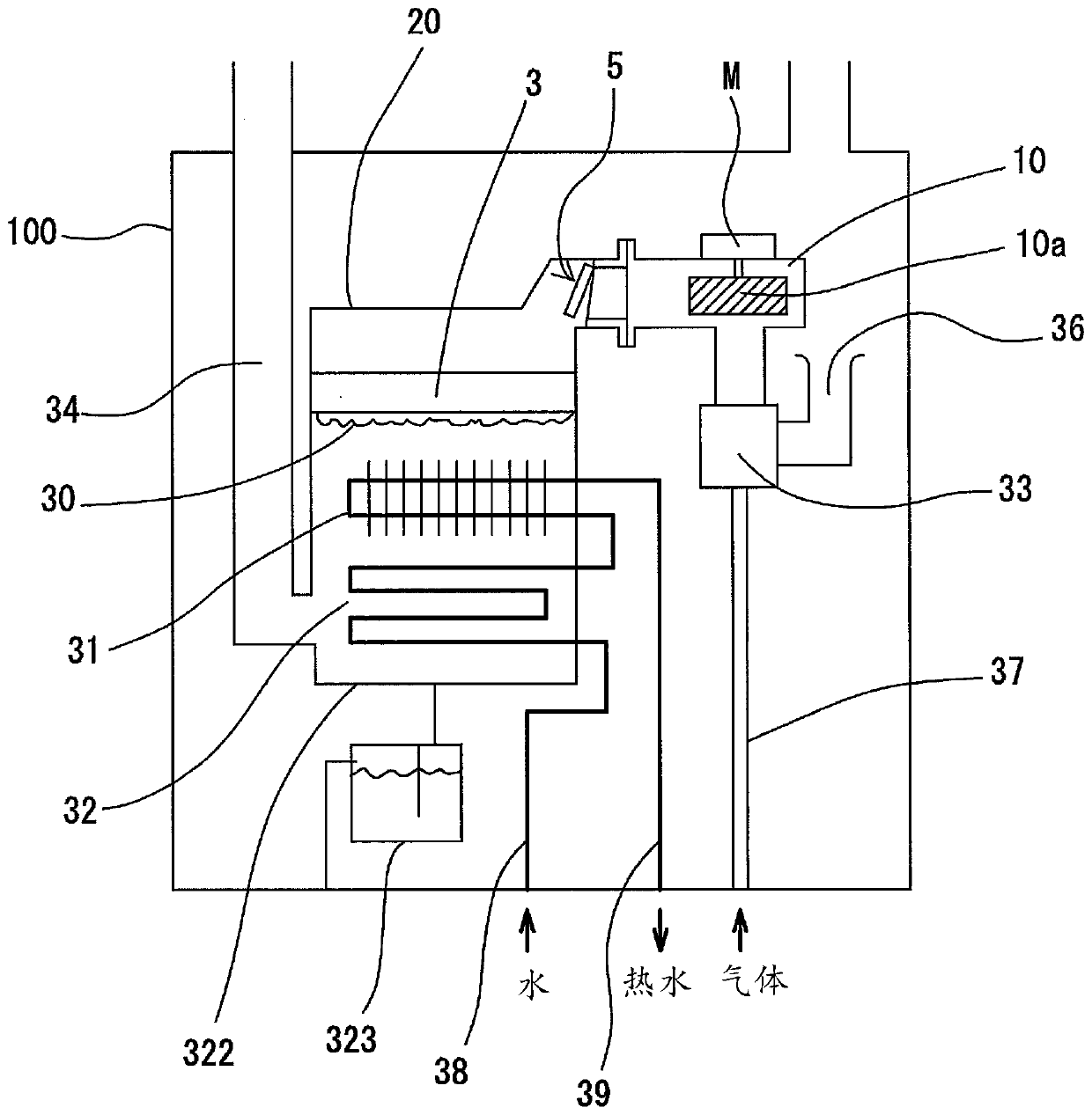
[0038] Hereinafter, with regard to the water heater according to the embodiment of the present invention, while referring to the attached Figure 1 Face specific instructions.

[0039] figure 1It is a schematic diagram of the latent heat recovery type gas water heater having the complete primary air combustion type burner 3 according to the first embodiment. Inside the housing 100 there is provided a container 20 provided with a burner 3 having a downwardly facing combustion face 30 and communicating therewith a fan housing 10 . Inside the fan case 10, a fan 10a that sends a mixture of air and fuel gas into the burner 3 inside the container 20 is housed. In addition, in this specification, along the flow path formed by the operation of the fan 10a, the side of the fan case 10 is called an upstream side, and the side of the container 20 is called a downstream side.

[0040] Below the burner 3 in the container 20, first and second heat exchangers 31 and 32 for hot water supp...


PUM


Abstract

The invention provides a water heater comprising: a container (20) equipped with a burner (3) with a downwardly facing combustion surface; a fan housing (10) containing primary air for combustion and fuel gas The fan (10a) that supplies the mixed gas to the burner; the annular gasket (6), which connects the first connection on the downstream end side of the first flow path (1) that forms the downstream side flow path of the fan casing (10) The end face (13) is connected in an airtight state with the second connecting end face (23) on the upstream end side of the second flow path (2) forming the upstream side flow path of the container (20); and the one-way valve (5), which It is installed near the upstream end in the second flow path (2).

Description

technical field [0001] The invention relates to a water heater. In particular, the present invention relates to a water heater having a burner of the all primary combustion type. Background technique [0002] Figure 9 It shows a latent heat recovery type in which a primary heat exchanger 311 of a sensible heat recovery type and a secondary heat exchanger 321 of a latent heat recovery type are arranged below the combustion surface 30a of a complete primary air combustion type burner 3a. Schematic diagram of a gas water heater. In this water heater, by rotating the fan (not shown) in the fan housing 41, all the air taken in from the air supply path 43 is sent into the mixing device 42 as primary air for combustion, and the sent air It is mixed with the combustion gas fed from the gas supply path 44 in the mixing device 42 . Then, the mixed gas is sent to the reverse combustion type burner 3a provided so that the combustion surface 30a faces downward. [0003] In the above...

Claims


Application Information

Patent Timeline
Patent Type & Authority Patents(China)
IPC IPC(8): F23K5/00F16L55/00
CPCF23K5/00F16L55/00F23L13/02F24H9/1836F24H9/2042F23D14/825F23D2209/10F24H1/145F24H8/006Y02B30/00F23D14/72F23K5/002F23K2900/05001F23K2400/20F24H15/345F24H15/136F23L5/02
Inventor 小代卓史
Owner RINNAI CORP
Why Eureka
Try Eureka