Full-automatic camshaft assembling machine

A camshaft, fully automatic technology, applied in assembly machines, laser welding equipment, manufacturing tools, etc., can solve problems affecting the use of camshafts, forming defective products, waste, etc., to improve machining accuracy, improve work efficiency, and ensure uniform speed sexual effect

Inactive Publication Date: 2018-02-23
DONGGUAN RONGGONG AUTOMATION TECH CO LTD
View PDF6 Cites 20 Cited by
  • Summary
  • Abstract
  • Description
  • Claims
  • Application Information

AI Technical Summary

Problems solved by technology

[0002] With the continuous progress of science and technology, the application of camshaft is more and more extensive, and it is also an important part of the valve train. The camshaft is assembled and processed by the cam and the shaft. The requirements are very high. If the alignment between the cam and the shaft is not accurate, it will affect the relative position accuracy of the cam and the shaft, and ultimately affect the use of the camshaft. The camshaft has high requirements on the quality of the shaft and the cam. The traditional processing flow Incoming material detection is rarely added during feeding, which is easy to form defective products. On the other hand, when the cam is usually pressed into the shaft groove, the cam and shaft are easy to cause crushing and scratches, resulting in loss and waste of materials. , which requires a camshaft assembly machine that can buffer the downward pressure, and can detect the finished product in time when the material is unloaded

Method used


Image

  • Full-automatic camshaft assembling machine
  • Full-automatic camshaft assembling machine
  • Full-automatic camshaft assembling machine

Examples


Embodiment Construction

[0040] In order to enable those skilled in the art to better understand the technical solution of the present invention, the present invention will be described in detail below in conjunction with the accompanying drawings. The description in this part is only exemplary and explanatory, and should not have any limiting effect on the protection scope of the present invention. .

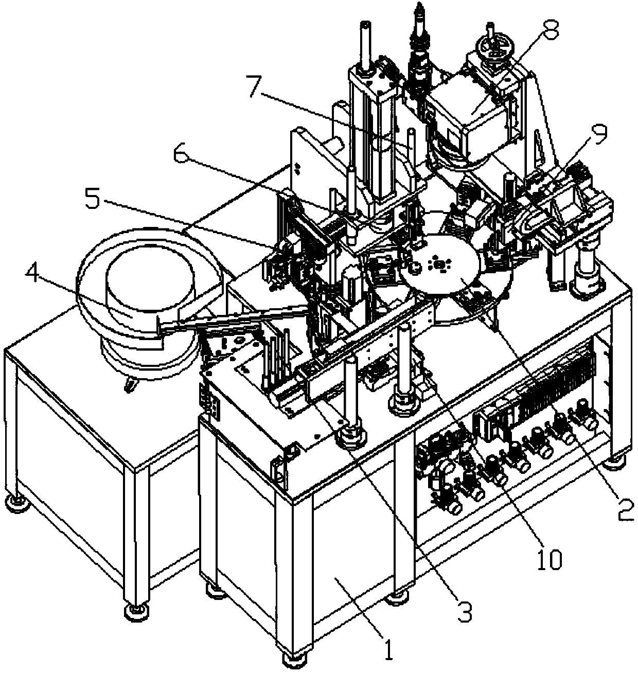
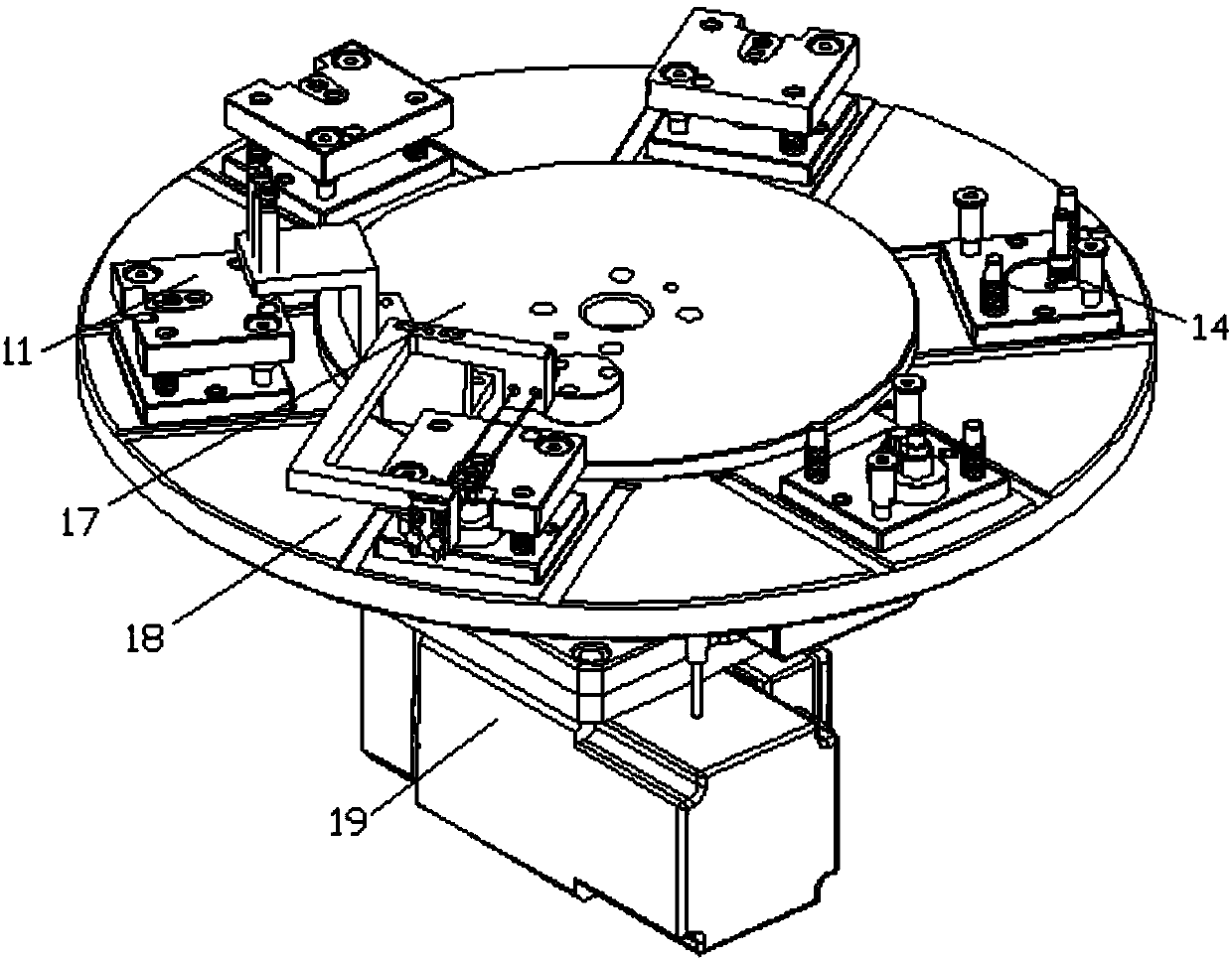
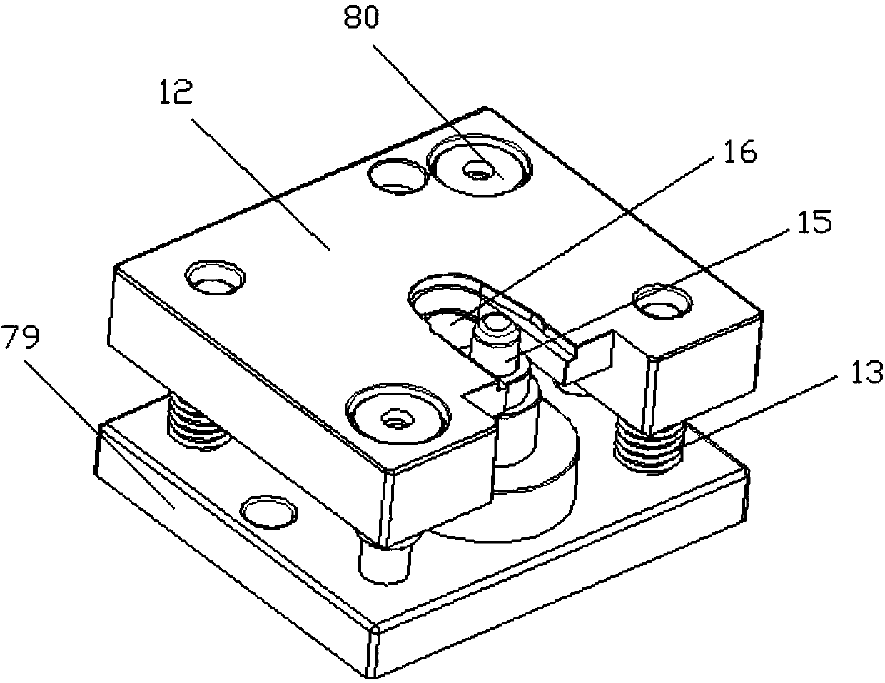
[0041] like Figure 1-Figure 14 As shown, the structure of the present invention is: a fully automatic camshaft assembly machine, which includes a frame 1 and a power distribution control box arranged in the frame 1, and the middle part above the frame 1 is provided with a turntable device 2, so The turntable device 2 includes a turntable operation motor 19 and a turntable 18 that are fixed on the frame 1 and cooperate with each other. A turntable fixing plate 17 fixed on the frame 1 is arranged above the turntable 18. The upper end of the turntable 18 is along the The carrier assembly 11 is evenly ar...


PUM


Abstract

The invention relates to a full-automatic camshaft assembling machine. The full-automatic camshaft assembling machine comprises a rack and a power distribution control cabinet arranged in the rack; arotating disk device is arranged on the middle portion above the rack; and a shaft feeding device, a cam vibrating feeding disk, a cam feeding device, a press-fitting device, a floating shaft pressingdevice, a laser welding device, a flaw detecting device and a discharging device in butt joint with carrier assemblies are sequentially arranged above the rack in the rotating direction of a rotatingdisk. According to the full-automatic camshaft assembling machine, by means of the shaft feeding device, a shaft is placed in the carrier assembly on the rotating disk device, and the carrier assembly rotates clockwise along the rotating disk and sequentially rotates onto the cam feeding device to perform cam feeding, onto the press-fitting device so as to press a cam into a matching groove of the shaft, onto the floating shaft pressing device to push down the shaft to be clamped with the matching groove, onto the laser welding device to perform laser welding on the matched portion of the shaft and the cam, onto the flaw detecting device to detect bruised damage and scratches, and onto the discharging device to perform discharging; and the assembling process of the cam and the shaft is completed, the positioning precision is high, and defective products are detected in time.

Description

technical field [0001] The invention relates to the field of assembly machines, in particular to a fully automatic camshaft assembly machine. Background technique [0002] With the continuous progress of science and technology, the application of camshaft is more and more extensive, and it is also an important part of the valve train. The camshaft is assembled and processed by the cam and the shaft. The requirements are very high. If the alignment between the cam and the shaft is not accurate, it will affect the relative position accuracy of the cam and the shaft, and ultimately affect the use of the camshaft. The camshaft has high requirements on the quality of the shaft and the cam. The traditional processing flow Incoming material detection is rarely added during feeding, which is easy to form defective products. On the other hand, when the cam is usually pressed into the shaft groove, the cam and shaft are easy to cause crushing and scratches, resulting in loss and waste...

Claims


Application Information

Patent Timeline
Patent Type & Authority Applications(China)
IPC IPC(8): B23P21/00B23K26/21B23K26/08
CPCB23P21/006B23K26/0884B23K26/21
Inventor 邓君杨坤
Owner DONGGUAN RONGGONG AUTOMATION TECH CO LTD
Why Eureka
Try Eureka