
Silencer and silencing method thereof

A muffler and noise reduction technology, which is applied in the direction of machines/engines, liquid displacement machinery, variable displacement pump components, etc., can solve the problems of complex muffler structure, difficult to clean, complex structure, etc., and achieve simple structure, light weight, good circulation effect

Pending Publication Date: 2018-02-23
台州宝乾机电股份有限公司
View PDF13 Cites 4 Cited by
  • Summary
  • Abstract
  • Description
  • Claims
  • Application Information

AI Technical Summary

Problems solved by technology

[0003] In the invention patent application with the application number 201210245981.7, a muffler for an air compressor is disclosed, which realizes noise reduction through the setting of a rotatable partition and the airflow holes placed on the partition; Noise reduction; finally, further noise reduction is achieved through a cylindrical sponge; and it solves the problems of traditional mufflers with complex structure, difficult cleaning, and high quality, but this air compressor muffler still has the following problems: the partition needs to be rotatable The rotatable mode requires external force to drive its rotation, and in order to increase its rotational stability, it is necessary to open holes and set a rotating shaft on the casing, which has a complex structure; it is necessary to set up a whirling groove to ensure that the The airflow can move repeatedly in the inner cavity; its noise reduction effect also needs to be improved

Method used


Image

  • Silencer and silencing method thereof
  • Silencer and silencing method thereof
  • Silencer and silencing method thereof

Examples


Embodiment Construction

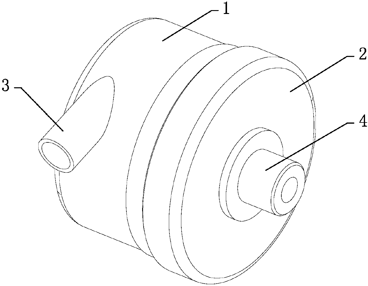
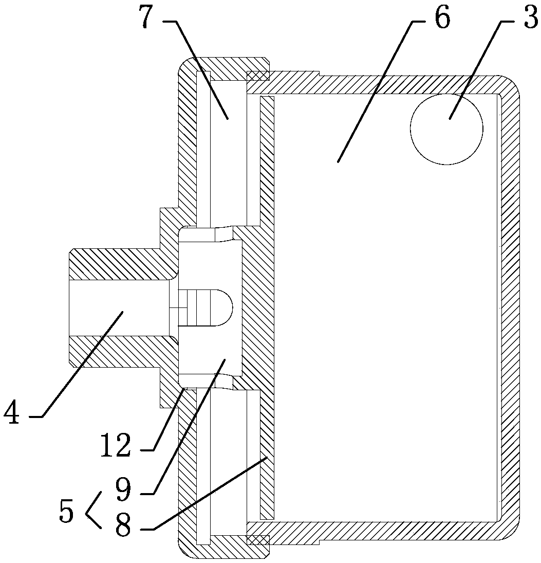
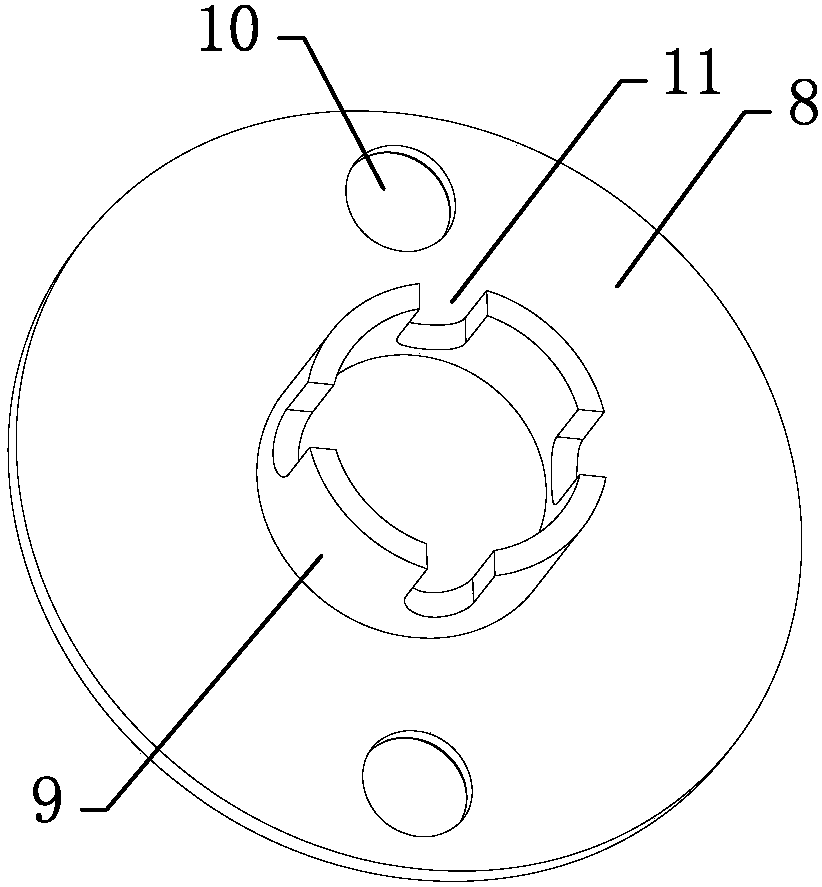
[0019] refer to Figures 1 to 3 A muffler embodiment of the present invention will be further described.

[0020] A muffler comprising an outer cover 1 and a fixing seat 2 placed on one end of the outer cover 1, the outer cover 1 is provided with an air inlet pipe 3, the fixing seat 2 is provided with an air outlet pipe 4, and the outer cover 1 is provided with a muffler 5, The muffler 5 includes a partition 8 separating the outer cover 1 into a first chamber 6 and a second chamber 7, a shunt cover 9 placed at the air inlet end of the air outlet pipe 4, the first chamber 6 communicates with the air inlet pipe 3 and the air inlet pipe The air inlet direction of 3 is set tangentially to the inner peripheral wall of the first chamber 6, the second chamber 7 communicates with the air outlet pipe 4, and the airflow hole connecting the first chamber 6 and the second chamber 7 is provided on the partition 8 10. A number of distribution holes 11 are provided on the side wall of the d...


PUM


Abstract

The invention discloses a silencer and aims to provide a silencer which is simple in structure and good in silencing effect. According to the key points of the technical scheme of the silencer, the silencer comprises an outer hood and a fixing seat placed on one side of the outer hood, an air inlet pipe is arranged on the outer hood, and an air outlet pipe is arranged on the fixing seat; a silencing device body is arranged in the outer hood and comprises a partition plate dividing the outer hood into a first cavity and a second cavity and a flow distributing hood placed at the air inlet end ofthe air outlet pipe; the first cavity communicates with the air inlet pipe, the air inlet direction of the air inlet pipe is tangent with the inner circumferential wall of the first cavity, and the second cavity communicates with the air outlet pipe; and the partition plate is provided with an air flow hole communicating with the first cavity and the second cavity, and the side wall of the flow distributing hood is provided with a plurality of flow distributing holes. The silencer is suitable for the technical field of air compressor parts.

Description

technical field [0001] The invention relates to the technical field of air compressor accessories, more specifically, it relates to a muffler and a muffler method thereof. Background technique [0002] The muffler is a noise reduction device installed in the intake and exhaust systems of aerodynamic equipment such as air compressors. [0003] In the invention patent application with the application number 201210245981.7, a muffler for an air compressor is disclosed, which realizes noise reduction through the setting of a rotatable partition and the airflow holes placed on the partition; Noise reduction; finally, further noise reduction is achieved through a cylindrical sponge; and it solves the problems of traditional mufflers with complex structure, difficult cleaning, and high quality, but this air compressor muffler still has the following problems: the partition needs to be rotatable The rotatable method requires external force to drive its rotation, and in order to inc...

Claims


Application Information

Patent Timeline
Patent Type & Authority Applications(China)
IPC IPC(8): F04B39/00
CPCF04B39/0083
Inventor 刘寿水
Owner 台州宝乾机电股份有限公司
Learn More