Penetration shearing device and method for foundation in-situ testing based on optical fiber and optical grating

A fiber grating, in-situ testing technology, used in measuring devices, using a stable shear force to test the strength of materials, instruments, etc., can solve the problems of limited application, short-circuiting of strain gauges, large artificial errors, etc., and achieve anti-electromagnetic interference. Strong ability, reduced disturbance, good waterproof effect

Pending Publication Date: 2018-02-23
NANJING UNIVERSTIY SUZHOU HIGH TECH INST
View PDF0 Cites 9 Cited by
  • Summary
  • Abstract
  • Description
  • Claims
  • Application Information

AI Technical Summary

Problems solved by technology

[0004] Generally speaking, the plate load test is the most direct and relatively accurate in-situ test method to determine the bearing capacity of the foundation, but this method is expensive, time-consuming and laborious, which limits its application in engineering
The cross-plate shear test is mostly manual operation, and the manual error is large
The electric cross-plate shear test and static penetration test that have appeared in recent yea

Method used


Image

  • Penetration shearing device and method for foundation in-situ testing based on optical fiber and optical grating
  • Penetration shearing device and method for foundation in-situ testing based on optical fiber and optical grating
  • Penetration shearing device and method for foundation in-situ testing based on optical fiber and optical grating

Examples


Embodiment

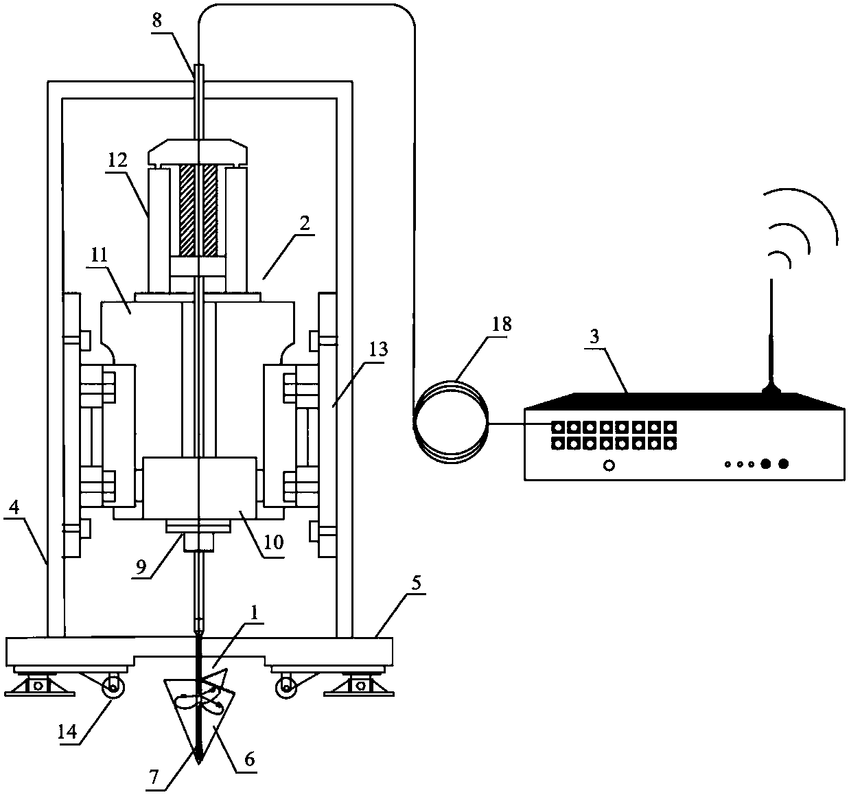
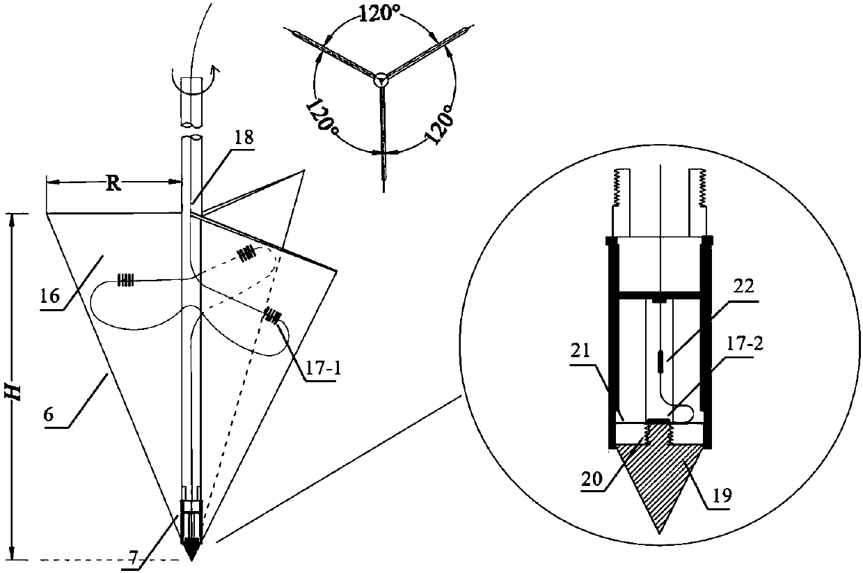
[0053] as attached figure 1 And attached figure 2 As shown, a penetration shearing device based on fiber gratings for foundation in-situ testing includes a multi-function probe 1 , a rotary drilling device 2 , a fiber grating wireless demodulator 3 , a chassis shell 4 and a base 5 . The multifunctional probe 1 includes a Y-shaped plate head 6 and a cone-point probe 7, and the cone-point probe 7 is installed at the bottom of the Y-shaped plate head 6; the rotary drilling device 2 includes a probe rod 8, Chuck 9, stepper motor 10, installation platform 11, press-in host 12, and fixing device 13; the probe rod 8 runs through the entire rotary drilling device 2 from bottom to top, and passes through the chuck 9, step The motor 10, the installation platform 11 and the press-in host 12 are connected to the bottom of the multi-function probe 1; the rotary drilling device 2 is installed on the inner wall of the chassis shell 4 through the fixing device 13; the chassis shell 4 is pla...


PUM


Abstract

The invention relates to a penetration shearing device and method for foundation in-situ testing based on the optical fiber and optical grating. The device comprises a multifunctional probe, a rotarydrilling device, an optical fiber and optical grating wireless interrogator, a machine case shell and a base. The multifunctional probe comprises a Y-shaped plate head and a conical tip testing head,and the conical tip testing head is arranged at the bottom of the Y-shaped plate head; the rotary drilling device comprises a feeler lever, a chuck, a stepping motor, a pressing-in main unit, a mounting platform and a fixing device; the feeler lever penetrates through the whole rotary drilling device from bottom to top and penetrates through the chuck, the stepping motor, the mounting platform andthe pressing-in main unit in sequence, and the bottom of the feeler lever is connected with the multifunctional probe; the in-situ testing method comprises the steps of site clearing, place taking, penetration and shearing. The multifunctional probe is downward pressed into soil layers with different depths in sequence, and the steps are repeated; the multifunctional probe is pulled out, and testing is completed. The penetration shearing device has the advantages of high precision, good stability, good waterproofness, high electromagnetic interference resistance, multi-parameter monitoring, automatic real-time monitoring and the like.

Description

[0001] Technology Neighborhood: [0002] The invention relates to the field of optical fiber sensing and foundation in-situ testing, in particular to a penetration shearing device and method for foundation in-situ testing based on an optical fiber grating. technical background: [0003] As a naturally occurring three-phase medium, soil generally has the characteristics of high moisture content, large void ratio, high compressibility, and low shear strength. It is very harmful in engineering construction, often causing foundation damage and slope loss. Stability and other issues. Therefore, it is an important subject in geotechnical engineering to quickly and effectively measure the physical and mechanical properties of foundation soil. At present, the commonly used foundation in-situ testing methods include plate load test, cross plate shear test and static penetration test. [0004] Generally speaking, the plate load test is the most direct and relatively accurate in-situ t...

Claims


Application Information

Patent Timeline
IPC IPC(8): G01N3/00G01N3/24
CPCG01N3/00G01N3/24
Inventor 朱鸿鹄周谷宇朱宝施斌
Owner NANJING UNIVERSTIY SUZHOU HIGH TECH INST
Why Eureka
Try Eureka