
Method for manufacturing deep trench and pn junction hybrid isolation structure for high-speed bipolar process

A bipolar process, isolation structure technology, applied in semiconductor/solid-state device manufacturing, electrical components, circuits, etc., can solve the problems of large isolation leakage current, high cost of all-dielectric isolation process, low yield of all-dielectric isolation process, etc. Achieve the effect of balancing the stress in the groove, reducing the process yield and increasing the complexity

Active Publication Date: 2020-03-31
NO 24 RES INST OF CETC
View PDF3 Cites 0 Cited by
  • Summary
  • Abstract
  • Description
  • Claims
  • Application Information

AI Technical Summary

Problems solved by technology

The existing technology usually uses full dielectric deep trench isolation to achieve high isolation effect. However, there are two main problems in full dielectric isolation. One is the high cost of full dielectric isolation process; low craft
As the most commonly used isolation method, PN junction isolation has the disadvantage of large isolation leakage current and cannot fully meet the design requirements. Therefore, a new technical means is urgently needed to solve the above technical problems.

Method used


Image

  • Method for manufacturing deep trench and pn junction hybrid isolation structure for high-speed bipolar process
  • Method for manufacturing deep trench and pn junction hybrid isolation structure for high-speed bipolar process
  • Method for manufacturing deep trench and pn junction hybrid isolation structure for high-speed bipolar process

Examples


Embodiment Construction

[0041] Embodiments of the present invention are described below through specific examples, and those skilled in the art can easily understand other advantages and effects of the present invention from the content disclosed in this specification. The present invention can also be implemented or applied through other different specific implementation modes, and various modifications or changes can be made to the details in this specification based on different viewpoints and applications without departing from the spirit of the present invention. It should be noted that, in the case of no conflict, the following embodiments and features in the embodiments can be combined with each other.

[0042] It should be noted that the diagrams provided in the following embodiments are only schematically illustrating the basic ideas of the present invention, and only the components related to the present invention are shown in the diagrams rather than the number, shape and shape of the compo...


PUM

PropertyMeasurementUnit
thicknessaaaaaaaaaa
thicknessaaaaaaaaaa
thicknessaaaaaaaaaa

Abstract

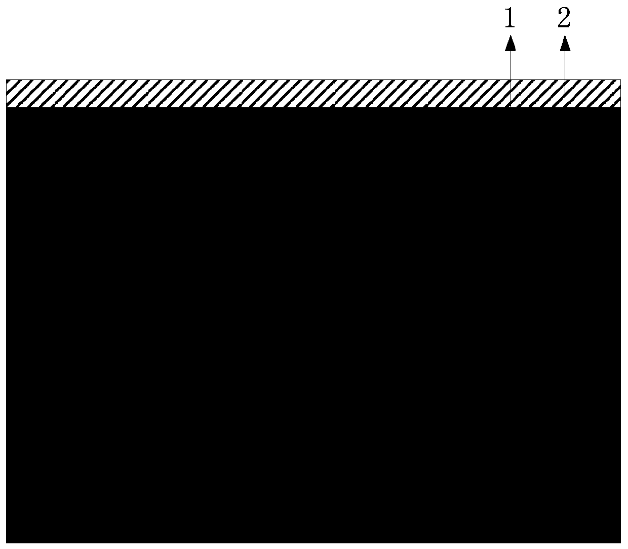
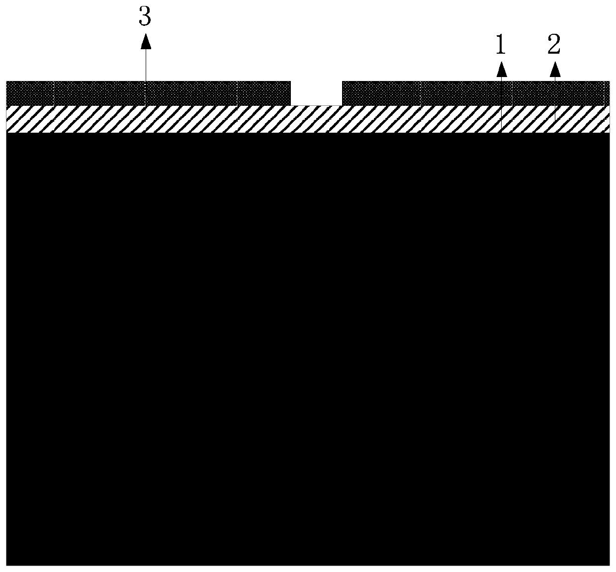
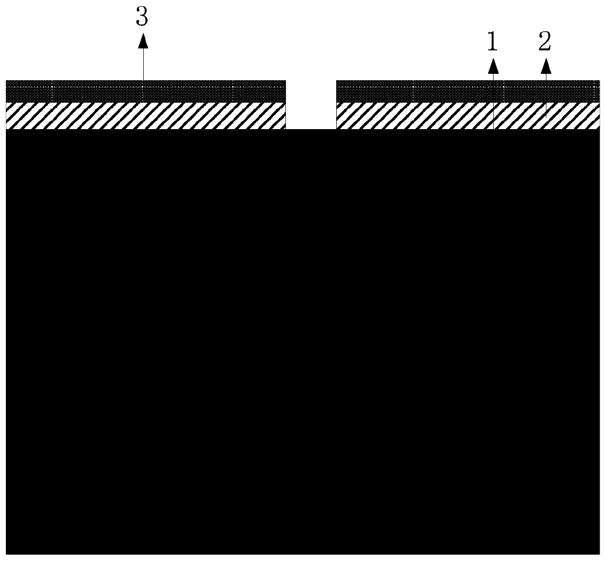
The invention provides a production method of a deep groove and PN junction mixed isolation structure for a bipolar technology. The method comprises the steps that a mask is arranged on a substrate silicon chip; an etching window running through the mask is arranged on the mask, the substrate silicon chip on the lower layer of the etching window is etched through the etching window, and a deep groove is formed; impurities whose doping type is opposite to that of bulk silicon are injected into the deep groove to form a groove bottom isolation PN junction; the mask is peeled off, and ONO composite film is prepared on the surface of the bulk silicon and in the deep groove; polycrystalline silicon is deposited to fill the deep groove; silicon oxide on the top layer of the ONO film outside thedeep groove is removed, and the remaining silicon nitride-silicon oxide structure is utilized to form an active area. According to the production method of the deep groove and PN junction mixed isolation structure for the bipolar technology, the stress in the groove is smartly balanced by means of the ONO structure on the inner wall of the deep groove, meanwhile the silicon nitride-silicon oxide structure is served as a masking layer of active area oxidation, extra production process of the masking layer during production of the active area is avoided, the production cost of the process is effectively reduced, and the isolation effect is improved.

Description

technical field [0001] The invention relates to the field of semiconductor analog integrated circuit manufacturing, in particular to a method for manufacturing a deep groove and PN junction hybrid isolation structure used in a high-speed bipolar process. Background technique [0002] In semiconductors, both majority and minority carriers (holes and electrons) participate in the conduction of active elements, such as the usual NPN or PNP bipolar transistors. Monolithic integrated circuits based on such transistors are called bipolar integrated circuits. Bipolar integrated circuits are fast and widely used in analog integrated circuits and digital integrated circuits. Galvanic isolation is required between components in bipolar integrated circuits. [0003] Among them, the deep trench isolation process has significant advantages: 1. Reduced device area and improved integration; 2. Reduced collector capacitance; 3. Increased breakdown voltage between collectors of bipolar tran...

Claims


Application Information

Patent Timeline
Patent Type & Authority Patents(China)
IPC IPC(8): H01L21/762
CPCH01L21/762
Inventor 张培健陈文锁易前宁梁柳洪冉明
Owner NO 24 RES INST OF CETC
Learn More