Control device for internal combustion engine

A control device and internal combustion engine technology, applied in engine control, fuel injection control, electrical control, etc., can solve problems such as air-fuel ratio deviation, achieve high-precision inference, and prevent the reduction of conversion efficiency

Active Publication Date: 2018-02-23
HITACHI ASTEMO LTD
View PDF10 Cites 2 Cited by
  • Summary
  • Abstract
  • Description
  • Claims
  • Application Information

AI Technical Summary

Problems solved by technology

When purging is performed, the evaporated fuel gas contained in the purge gas is introduced into the combustion chamber, so the air-fuel ratio will shift unless the amount of fuel injected from the fuel injection valve is reduced

Method used


Image

  • Control device for internal combustion engine
  • Control device for internal combustion engine
  • Control device for internal combustion engine

Examples


Embodiment 1

[0039] Next, a first embodiment of the present invention will be described with reference to the drawings.

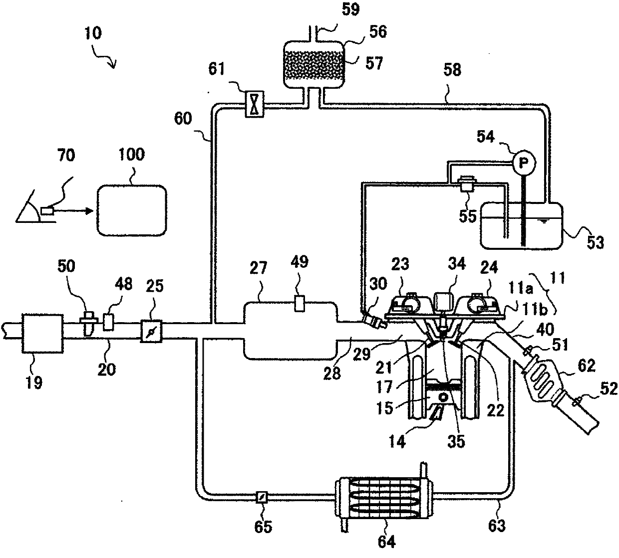
[0040] figure 1 It is an overall configuration diagram of an internal combustion engine equipped with a control device for an internal combustion engine according to the present invention.

[0041] The internal combustion engine 10 is, for example, a spark ignition multi-cylinder internal combustion engine equipped with four cylinders, and includes a cylinder 11 composed of a cylinder head 11a and a cylinder block 11b, and a piston 15 slidably inserted into each cylinder of the cylinder 11. The piston 15 passes through The connecting rod 14 is connected to a crankshaft (not shown). Also, above the piston 15 is formed a combustion chamber 17 having a top plate portion of a predetermined shape, and inside the combustion chamber 17 of each cylinder, a spark plug 35 to which a high-voltage ignition signal is supplied from an ignition coil 34 is placed downward.

[0042] I...

Embodiment 2

[0135] Next, a second embodiment will be described below with reference to the drawings. The overall composition of the internal combustion engine has removed the EGR systems such as the EGR pipeline 63, the EGR cooler 64, and the EGR valve 65. figure 1 same.

[0136] Figure 10 In order to use the relative humidity of the first humidity sensor 48 and the second humidity sensor 49 respectively provided upstream and downstream of the connecting portion of the intake pipe 20 and the purge introduction pipe 60 to estimate the fresh air and blown air at the downstream of the connecting portion. Flowchart for controlling the fuel injection amount based on the purge air-fuel ratio, which is the ratio of the purge gas, and the estimated purge air-fuel ratio.

[0137] In S1001, the relative humidity RH is read from the first humidity sensor 48 amb , temperature T amb , pressure P amb , move to the next step.

[0138] In S1002, the relative humidity RH is read from the second hum...

Embodiment 3

[0173] Next, a third embodiment will be described below with reference to the drawings. The overall composition of the internal combustion engine has removed the EGR systems such as the EGR pipeline 63, the EGR cooler 64, and the EGR valve 65. figure 1 same.

[0174] Figure 12 In order to use the absolute humidity of the first humidity sensor 48 and the second humidity sensor 49 respectively provided upstream and downstream of the connection part of the intake pipe 20 and the purge introduction pipe 60 to estimate the fresh air and blown air at the downstream of the connection part. Flowchart for controlling the fuel injection amount based on the purge air-fuel ratio, which is the ratio of the purge gas, and the estimated purge air-fuel ratio.

[0175] In S1201, read the air volume signal Q detected by the air flow sensor 50 a, move to the next step. Air quantity signal Q a The unit is [g / s].

[0176] In S1202, read the purge flow signal Q b , move to the next step. P...


PUM


Abstract

With an EGR rate estimation method using the opening size of an EGR valve, the EGR rate estimation accuracy deteriorates as the EGR valve worsens, and when the target EGR rate is high, the accuracy demanded cannot be achieved. In addition, with a method for correcting an injection amount with respect to a fuel injection valve by estimating a purge air-fuel ratio from the change in air-fuel ratio occurring when purging is performed or not performed, when the concentration of fuel evaporation gas adsorbed on activated carbon within a canister is high, fuel injection correction cannot keep up with the change in the air-fuel ratio, and the conversion efficiency of a catalyst decreases. An intake pipe of the present invention has an introduction port at which gas other than new air flows into the intake pipe. Humidity sensors are provided on the upstream and downstream of the introduction port, and the purge air-fuel ratio or the EGR rate inside the intake pipe is estimated by using sensorvalues obtained from the respective humidity sensors.

Description

technical field [0001] The present invention relates to control of an internal combustion engine in which a plurality of humidity sensors for measuring the humidity inside the intake pipe of the internal combustion engine are mounted on an intake pipe and the values ​​of the humidity sensors are used. Background technique [0002] In recent years, the control of fuel efficiency and emissions of vehicles such as automobiles has been continuously strengthened, and this control will also tend to be strengthened in the future. In particular, fuel efficiency has received a lot of attention due to the rise in gasoline prices, the impact on global warming, and the problem of energy depletion. [0003] Under such circumstances, countries all over the world are developing various technologies aimed at improving the fuel efficiency of vehicles. Examples of such developed technologies include electrification and compression ratio improvement represented by hybrid vehicles and electric ...

Claims


Application Information

Patent Timeline
Patent Type & Authority Applications(China)
IPC IPC(8): F02M26/46F02D41/04F02D41/14F02D43/00F02D45/00F02M25/08F02P5/15
CPCF02M26/46F02D41/0072F02D2200/0418F02D2200/0414F02D41/0042F02D41/0045F02D41/0002F02M26/17F02M25/089F02P5/1516F02P5/045F02D41/04F02D41/14F02D43/00F02D45/00F02P5/15F02M25/08F02D41/0077F02D41/144
Inventor 真户原伸也赤城好彦浅野诚二押领司一浩
Owner HITACHI ASTEMO LTD
Why Eureka
Try Eureka