
Real-time fluorescent quantitation PCR (polymerase chain reaction) instrument

A technology of real-time fluorescence quantification and light emission, which is applied in the field of optical detection, can solve the problems of increasing material cost, optical path cross interference, and affecting detection results, etc., to achieve the effect of eliminating individual differences, solving spherical aberration, and avoiding cross interference

Pending Publication Date: 2018-03-02
鲲鹏基因(北京)科技有限责任公司 +1
View PDF0 Cites 17 Cited by
  • Summary
  • Abstract
  • Description
  • Claims
  • Application Information

AI Technical Summary

Problems solved by technology

Generally, there are several ways to realize this structure. One is that the lens and detection structure at the receiving end are separated for each channel, so that different detection structures will have differences between devices, and will increase material costs.
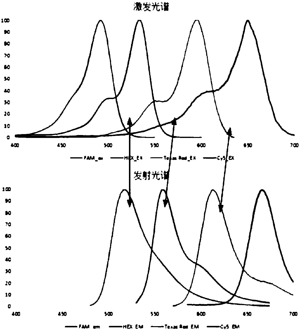
The second is to use the same excitation light source or detection device. Due to the multiplexing of the device, there will be no device difference, but the design of the optical lens and structure is prone to optical path difference and cross interference between optical paths. Specifically, due to the use of optical filters Rotary wheel gating structure, which is often the way of imaging. Due to the difference in optical path difference between the 96-well and the excitation light source and detection device, the excitation and reception efficiency are also different, which will affect the detection results. The collection lens often adopts a plano-convex lens, so due to the different distances and positions of multiple optical paths from the plano-convex lens, it will also cause differences and phase differences in excitation light intensity and collection efficiency; In 500-700nm, integrating 5-6 optical channels in this range will inevitably cause the intersection of the fluorescence collection filter spectrum of the low-band optical channel and the excitation filter spectrum of the adjacent high-band optical channel. phenomenon, see figure 1 , the place marked by the arrow is the case where the spectra intersect
From our optical structure, when there is this intersection, the excitation light of each optical channel will be cut off by the fluorescence collection filter corresponding to the channel, and will not be collected by the detection device. However, it is found in practical applications that even When the white-walled EP tube is used, when the LED of the optical reading head excites the EP tube under it (this EP tube is the target tube to be tested), the excitation light will pass through the tube wall of the target tube to be tested, so that the excitation light crosstalks to other phases. Among the adjacent EP tubes, the crosstalked EP tube is called a crosstalk tube. At this time, if there is another collecting optical path on the heat cover through hole facing the top cover of the crosstalking EP tube, the spectrum of this optical path is the same as that to be The detection optical path is adjacent to and in front of it, that is, the fluorescence collection filter of the optical path corresponding to the top of the crosstalk tube intersects with the excitation light filter of the optical path corresponding to the tube to be detected, then the excitation light crosstalked by the target tube to be detected is It will be received by the same detection device through the fluorescence collection filter corresponding to the optical path on the crosstalk tube, resulting in crosstalk of the optical channel

Method used


Image

  • Real-time fluorescent quantitation PCR (polymerase chain reaction) instrument
  • Real-time fluorescent quantitation PCR (polymerase chain reaction) instrument
  • Real-time fluorescent quantitation PCR (polymerase chain reaction) instrument

Examples


Embodiment Construction

[0031] In order to make the purpose, technical solutions and advantages of the present invention clearer, the following technical solutions in the present invention are clearly and completely described. Obviously, the described embodiments are some embodiments of the present invention, rather than all embodiments. Based on the embodiments of the present invention, all other embodiments obtained by persons of ordinary skill in the art without creative efforts fall within the protection scope of the present invention.

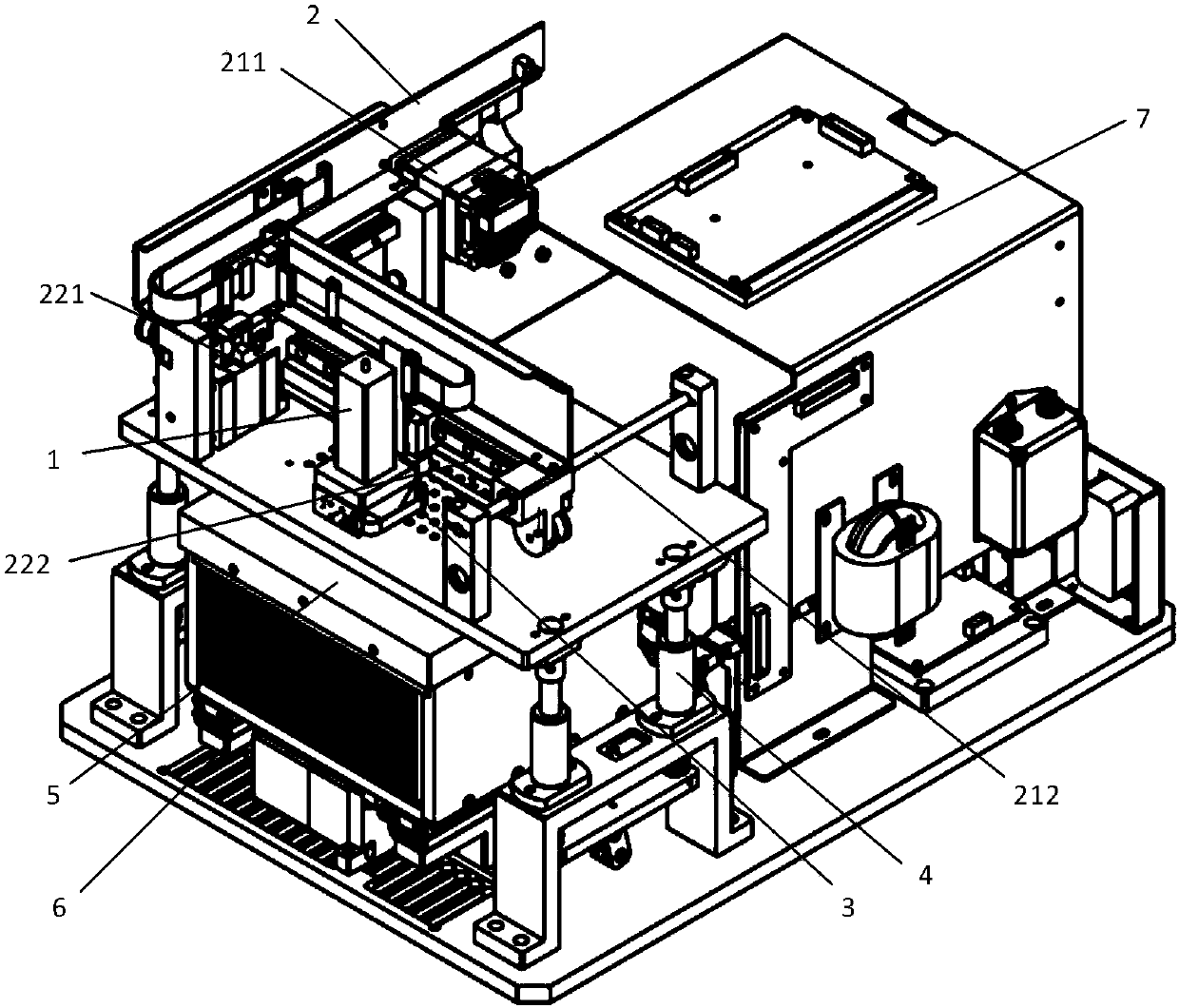
[0032] see Figure 9 , the real-time fluorescent quantitative PCR instrument provided by the present invention is mainly divided into upper and lower parts, above which is a thermal cover and a scanning head, wherein the scanning head can be controlled by a motor to move along the X-axis and the Y-axis on a two-dimensional plane. The hot cover can provide a high temperature of about 100 degrees to prevent the PCR system in the EP tube from vaporizing and forming ...


PUM


Abstract

The invention provides a real-time fluorescent quantitation PCR (polymerase chain reaction) instrument, which comprises a light read head, wherein the light read head consists of at least two light detecting passages; each light detecting passage comprises an excitation light source, a dichroscope, an emitting light lens and a detecting device; after the excitation light of the excitation light source is directly irradiated on the dichroscope; after the light path direction is converted by the dichroscope, the excitation light is vertically irradiated onto a target of an EP pipe of a pipe to be detected; after the light reflected from the target of the EP pipe of the pipe to be detected sequentially passes through the dichroscope and the emitting light lens and then enters the detecting device for detection, wherein each light detecting passage shares the emitting light lens and the detecting device; the emitting light lens comprises a Fresnel lens. The light collecting efficiency of each light passage is approximate; the problem of spherical surface phase difference of a convex lens is effectively solved; the individual difference among the devices is eliminated by the same detecting device; through the arrangement of light path position, the cross interference among light paths is effectively avoided.

Description

technical field [0001] The invention relates to the technical field of optical detection, in particular to a real-time fluorescence quantitative PCR instrument. Background technique [0002] Polymerase chain reaction (PCR), as a common analysis method in molecular biology, has been widely used in scientific research and clinical fields. Most of the follow-up PCR uses electrophoresis for qualitative and semi-quantitative analysis. Due to the impossibility of quantitative analysis and possible contamination caused by opening the cover, a real-time fluorescent quantitative PCR system came into being. At present, most of the real-time fluorescent quantitative PCR instruments on the market have multi-color fluorescent channels, which can perform multiple PCR and allele, SNP and other analysis at the same time, and the required detection results can be obtained in one experiment. A PCR instrument using multi-color detection generally includes multiple detection optical paths, and...

Claims


Application Information

Patent Timeline
IPC IPC(8): C12M1/38C12M1/36C12M1/34
CPCB01L7/52B01L2300/0654B01L2300/1894B01L2300/1822Y02A50/30
Inventor 郭求真戴涛
Owner 鲲鹏基因(北京)科技有限责任公司
Learn More