A control method of dendrite spacing during the growth process of Ni-based single crystal superalloy

A dendrite spacing, superalloy technology, applied in the direction of single crystal growth, single crystal growth, crystal growth, etc., can solve problems such as dendrite coarsening, and achieve the effect of controlling dendrite coarsening

Active Publication Date: 2020-11-03
INST OF METAL RESEARCH - CHINESE ACAD OF SCI
View PDF2 Cites 0 Cited by
  • Summary
  • Abstract
  • Description
  • Claims
  • Application Information

AI Technical Summary

Problems solved by technology

[0003] The object of the present invention is to provide a method for controlling dendrite spacing in the growth process of Ni-based single crystal superalloy, which solves the problem caused by the change of dendrite growth path in the process of directional solidification of single crystal superalloy by controlling the dendrite spacing. dendrite coarsening problem

Method used


Image

  • A control method of dendrite spacing during the growth process of Ni-based single crystal superalloy
  • A control method of dendrite spacing during the growth process of Ni-based single crystal superalloy
  • A control method of dendrite spacing during the growth process of Ni-based single crystal superalloy

Examples


Embodiment 1

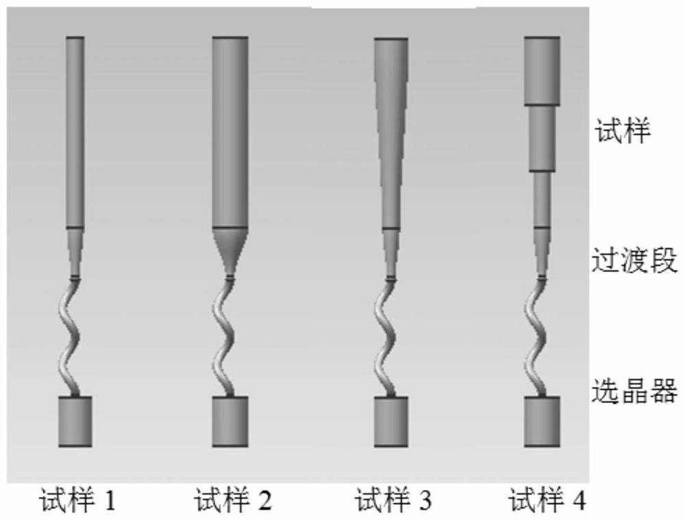
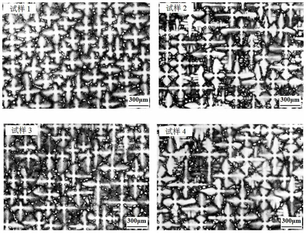
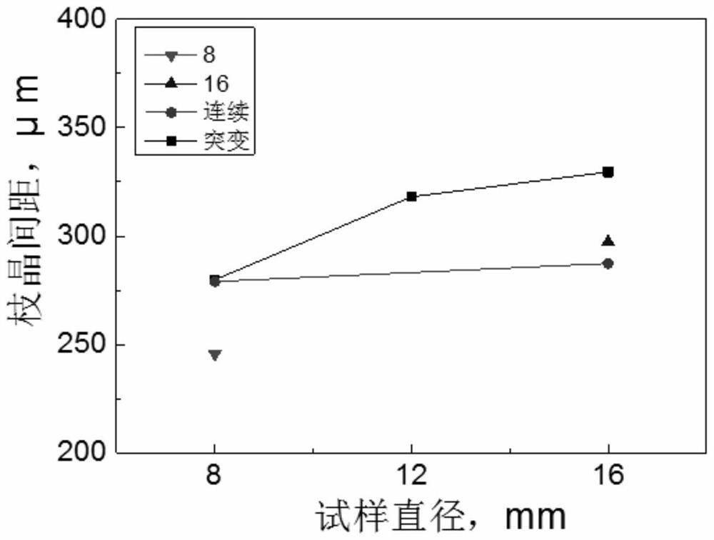
[0026] Such as figure 2 As shown, under the condition that the directional solidification process is unchanged, the dendrite growth path is different with the different sample size, resulting in different dendrite spacing in the single crystal test bar. Such as image 3 As shown, when the dendrite grows in the sample 1 with a size of φ8, the dendrites are fine and dense, and the dendrite spacing is about 246μm; when the dendrites grow in the sample 2 with a size of φ16, the dendrites are significantly coarsened , The dendrite spacing is about 297μm; when the dendrite is grown in sample 3 with a size of φ8-16 continuously expanded, the dendrite morphology is similar to that of sample 3, and the dendrite spacing is about 287μm; when the dendrite is in size When growing in sample 4 with a φ8-16 mutation expansion, the dendrites are coarser, and the dendrite spacing is about 330μm. When the sample size is in the range of φ8-16mm, as the sample size increases, the dendrite spacing ...

Embodiment 2

[0028] According to the difference between the dendrite spacing in different growth paths of dendrite in Example 1, adjust the single crystal growth mode in the simulated blade, from the top tenon to the bottom tenon, such as Figure 4 Shown. Due to the different growth methods, the dendrite spacing in the leaves also has significant differences. Figure 5 It is the dendrite morphology of leaf simulation pieces with different growth methods. In the blade simulation part of the tenon-up growth mode, the dendrite is relatively fine and dense, and the dendrite spacing is about 280μm; in the blade simulation part of the tenon-down growth mode, the dendrite is relatively coarse, and the dendrite spacing is about 300μm. Therefore, by changing the growth mode of the blade simulation piece, the goal of controlling the dendrite spacing can be achieved.


PUM

PropertyMeasurementUnit
diameteraaaaaaaaaa

Abstract

The invention discloses a control method for dendritic crystal spacing in a growth process of a Ni-based single-crystal high-temperature alloy, and belongs to the technical field of single-crystal high-temperature alloys. The method aims to the Ni-based single-crystal high-temperature alloy, and achieves the purpose of controlling the dendritic crystal spacing through adjusting a dendritic crystalgrowth path in the process of directional solidification; and when dendritic crystals of a Ni-based single-crystal casting are coarsened, the method can adjust the dendritic crystal spacing through changing a single-crystal casting growth mode. The method provided by the invention achieves the purpose of controlling the dendritic crystal spacing through adjusting the dendritic crystal growth path, and lays a foundation for preparing single-crystal structural parts with variable cross-section characteristics in the future.

Description

Technical field [0001] The invention relates to the technical field of single crystal superalloys, in particular to a method for controlling dendrite spacing during the growth of Ni-based single crystal superalloys. Background technique [0002] In order to meet the requirements of advanced aero-engine turbine blades for temperature resistance, single-crystal superalloys that eliminate grain boundaries, a high-temperature and weak structure, have gradually become the material of choice for the preparation of advanced aero-engine turbine blades due to their excellent high-temperature performance. The design structure and manufacturing quality of single crystal superalloy turbine blades directly affect the temperature-bearing capacity and overall performance of aeroengines. Throughout the development history of advanced aero-engines, the large-scale size and complex structure of single-crystal superalloy turbine blades have become an effective means and an inevitable trend to conti...

Claims


Application Information

Patent Timeline
Patent Type & Authority Patents(China)
IPC IPC(8): C30B11/00C30B29/52
CPCC30B11/006C30B29/52
Inventor 孟祥斌李金国刘纪德张朝威王猛赵乃仁王志辉金涛孙晓峰
Owner INST OF METAL RESEARCH - CHINESE ACAD OF SCI
Why Eureka
Try Eureka