Heat exchange device and semiconductor refrigeration equipment with same

A heat exchange device and heat exchange surface technology, applied in heat exchange equipment, lighting and heating equipment, refrigerators, etc., can solve the problems of unsuitable installation, pull down to 12°C, large installation space, etc., and reduce the front and rear thickness And the total volume, increase the air flow, increase the effect of air velocity

Inactive Publication Date: 2018-03-06
QINGDAO HAIER SMART TECH R & D CO LTD
View PDF4 Cites 3 Cited by
  • Summary
  • Abstract
  • Description
  • Claims
  • Application Information

AI Technical Summary

Problems solved by technology

However, the defect of the prior art is that the cooling fin itself has a large volume, and an axial flow fan needs to be installed on one side of the cooling fin to blow the airflow to the gap between the adjacent two fins, or to blow air from the adjacent two fins. The gap between the fins draws in the airflow
This kind of heat exchanger has a relatively large volume and requires a large installation space, so it is not suitable for installation in a small space.
In addition, the heat dissipation of the hot end of the semiconductor cooling chip is usually achieved by increasing the speed and power of the fan to achieve the purpose of heat dissipation, which has poor heat dissipation efficiency and high noise and high energy consumption.
[0005] Moreover, the existing technology cannot effectively solve the heat dissipation problem of the semiconductor refrigeration sheet with high heat flux density, so that the semiconductor refrigeration capacity cannot be guaranteed.
For example, the volume of conventional semiconductor refrigeration refrigerators is generally less than or equal to 50L. When the ambient temperature is 32°C, the temperature inside the refrigerator can only be lowered to 12°C, which cannot achieve a lower temperature, resulting in the inability to realize large volume (volume greater than 50L) semiconductor refrigeration refrigerator

Method used


Image

  • Heat exchange device and semiconductor refrigeration equipment with same
  • Heat exchange device and semiconductor refrigeration equipment with same
  • Heat exchange device and semiconductor refrigeration equipment with same

Examples


Embodiment Construction

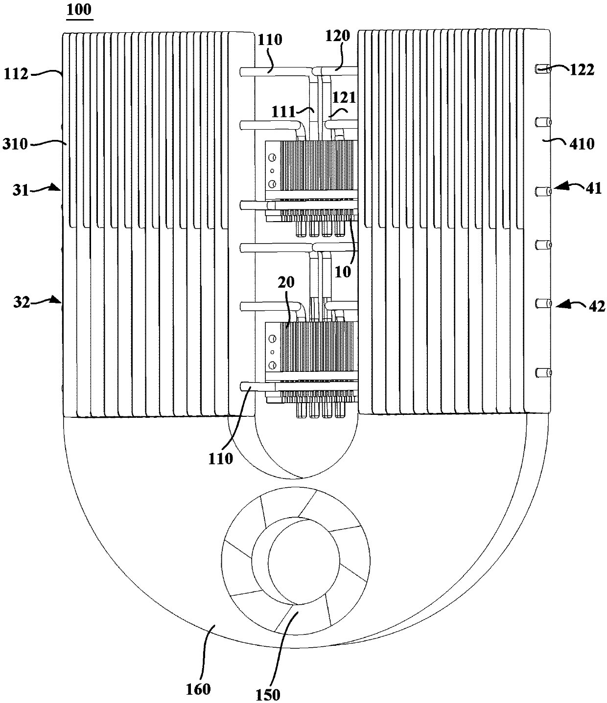
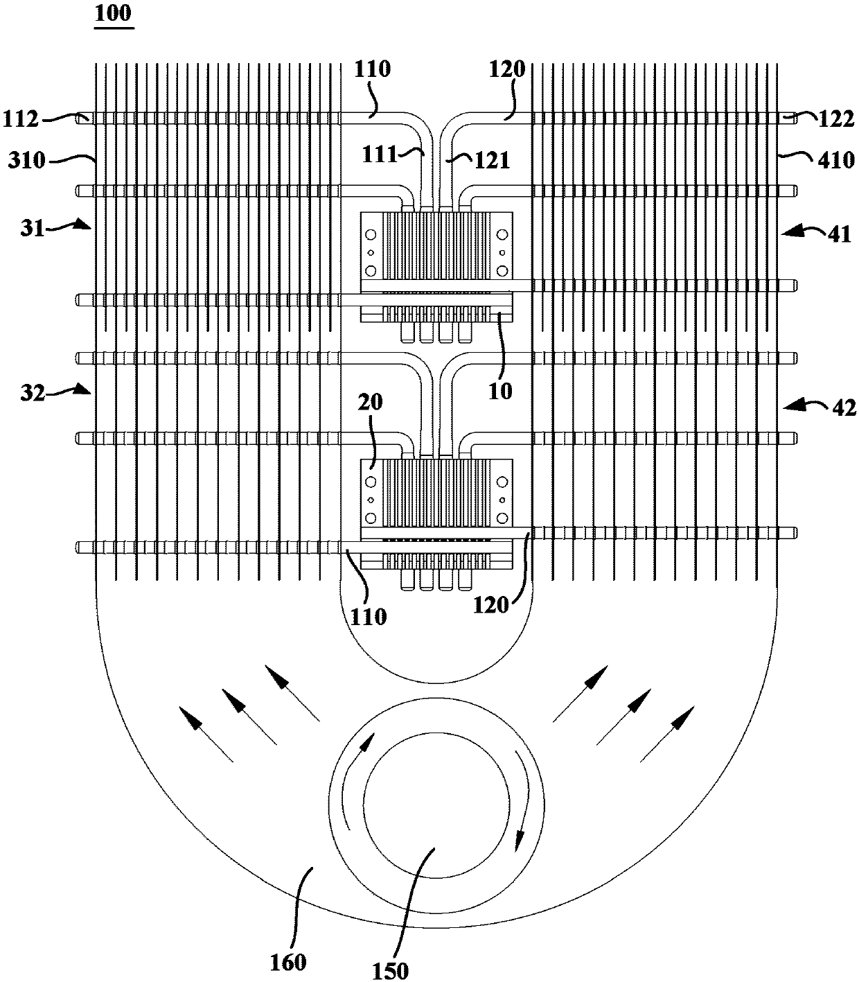
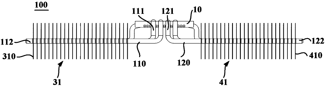
[0049] figure 1 is a schematic structural diagram of a heat exchange device 100 according to an embodiment of the present invention; figure 2 yes figure 1 A schematic front view of the heat exchange device 100 shown; image 3 yes figure 1 A schematic top view of the heat exchange device 100 shown. Such as Figure 1 to Figure 3 As shown, the heat exchange device 100 may include: at least one heat transfer substrate, at least one first heat pipe 110 , a first cooling fin group, and a fan 150 .

[0050] The heat transfer substrate has a heat exchange surface thermally connected to the heat source to receive heat from the heat source. The first heat pipe 110 has a connection section 111 thermally connected to a heat transfer substrate and a heat dissipation section 112 extending from one end of the connection section 111 toward one lateral side of the heat transfer substrate. The connection section 111 and the heat dissipation section 112 may be directly connected through a...


PUM


Abstract

The invention provides a heat exchange device and semiconductor refrigeration equipment with the heat exchange device. The heat exchange device comprises at least one heat transfer substrate, at leastone first heat pipe, a first cooling fin set and a fan. Each heat transfer substrate is provided with a heat exchange face in hot connection with heat sources to receive heat from the corresponding heat sources. Each first heat pipe is provided with a connecting section connected with one heat transfer substrate and a heat radiation section extending from one end of the connecting section to thetransverse side of the heat transfer substrate. The first cooling fin set comprises a plurality of first cooling fins which vertically extend and are arranged in the transverse direction at intervals,and the first cooling fin set is arranged on the heat radiation sections of the first heat pipes to dissipate heat transmitted from the connecting sections to the heat radiation sections. The fan isarranged above or below at least one heat transfer substrate and/or the first cooling fin set and configured to drive air flow to vertically flow in a clearance between any two adjacent first coolingfins. The thickness of the heat exchange device can be reduced, and the heat radiation efficiency of the heat exchange device can be improved.

Description

technical field [0001] The invention relates to heat exchange technology, in particular to a heat exchange device and semiconductor refrigeration equipment with the heat exchange device. Background technique [0002] In recent years, semiconductor refrigeration equipment has been widely used due to its superior performance, such as semiconductor refrigeration refrigerators, semiconductor refrigeration freezers, etc. Semiconductor refrigeration equipment uses the automatic variable pressure and variable flow control technology of semiconductor refrigeration chips to achieve refrigeration, and at the same time realizes heat dissipation through heat pipes and conduction technology, without the need for refrigeration refrigerants and mechanical moving parts. Therefore, semiconductor refrigeration equipment does not have a series of problems in the application of traditional mechanical refrigeration equipment such as working fluid pollution and mechanical vibration during applica...

Claims


Application Information

Patent Timeline
Patent Type & Authority Applications(China)
IPC IPC(8): F28D15/02F28F1/30F25B21/02
CPCF28D15/02F25B21/02F25B2321/003F25B2321/025F28D15/0275F28F1/30
Inventor 裴玉哲王定远刘永辉刘杰张立臣
Owner QINGDAO HAIER SMART TECH R & D CO LTD
Why Eureka
Try Eureka