Half-bridge flyback resonant circuit

A resonant circuit and circuit technology, applied in the direction of electrical components, adjusting electrical variables, high-efficiency power electronic conversion, etc., can solve the problems of high voltage stress of switching tubes, poor voltage cross-regulation rate, low efficiency, etc., to improve efficiency and improve EMI , cost reduction effect

Inactive Publication Date: 2018-03-06
SHENZHEN SINEXCEL ELECTRIC
View PDF5 Cites 12 Cited by
  • Summary
  • Abstract
  • Description
  • Claims
  • Application Information

AI Technical Summary

Problems solved by technology

[0003] The flyback circuit has the following defects: the switch tube works in a hard switching state, generates a lot of heat, and has low efficiency, so a radiator needs to be added to the switch tube; the EMI effect is poor; the voltage stress of the switch tube Q1 is high, and the rated voltage is generally selected to be greater than 2 *Vin voltage switching tube
When the input voltage is high (such as 1000V), it is difficult to find a suitable switch tube
[0004] The forward circuit has the following defects: the switching tube works in a hard switching state, generates a lot of heat, and has low efficiency, so a radiator needs to be added to the switching tube; the EMI effect is poor; additional reset windings or clamping circuits need to be a

Method used


Image

  • Half-bridge flyback resonant circuit
  • Half-bridge flyback resonant circuit
  • Half-bridge flyback resonant circuit

Examples


Embodiment 1

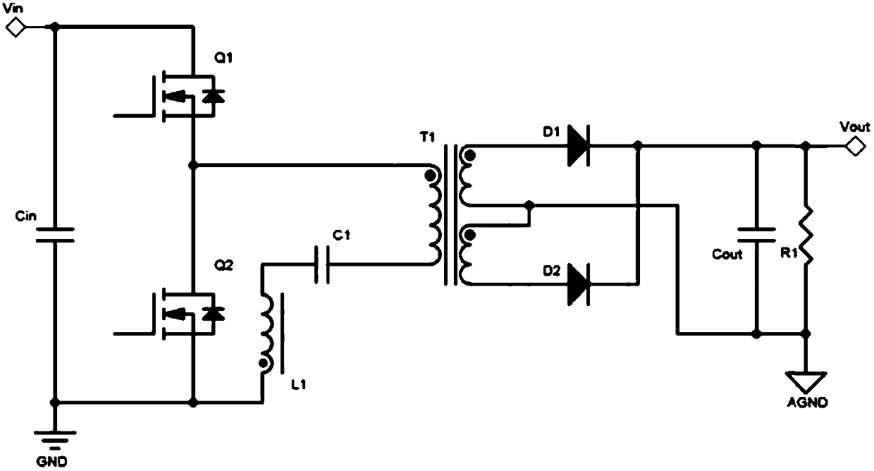
[0041] reference Figure 5 In the first embodiment, the half-bridge flyback resonant circuit mainly includes a half-bridge circuit 100, a primary input circuit 200, and a flyback secondary circuit 300. The half-bridge circuit 100 includes an upper bridge arm and a lower bridge arm. The primary input circuit 200 is connected in parallel with the lower bridge arm and includes an energy storage element and the primary winding of the flyback transformer T1. The structure of the flyback secondary circuit 300 is the same as that of the conventional flyback circuit.

[0042] Specifically, a capacitor Cin is connected between the positive terminal Vin and the negative terminal of the input power source (ie, the ground GND of the input power terminal). The switching element of the upper arm of the half-bridge circuit 100 is specifically an N-type MOS transistor Q1. The switching element specifically uses an N-type MOS tube Q2. The drain of the MOS transistor Q1 is connected to the posit...

Embodiment 2

[0052] reference Image 6 Compared with the first embodiment, the second embodiment differs in that the current sampling resistor R2 is added to facilitate the feedback adjustment of the switching power supply terminal. Specifically, the drain of the MOS transistor Q1 is connected to the positive Vin of the input power source, the source of the MOS transistor Q1 is connected to the drain of the MOS transistor Q2, and the source of the MOS transistor Q2 is connected to the primary side of the flyback transformer T1 through the capacitor C1. The opposite end of the winding is connected to one end of the current sampling resistor R2 on the other hand, and the other end of the current sampling resistor R2 is connected to GND.

Embodiment 3

[0054] reference Figure 7 Compared with the first embodiment, the third embodiment is different in that the number of the flyback secondary circuit is two. Specifically, the first flyback secondary circuit 300 includes a first secondary winding, a diode D1, a capacitor Cout, and a resistor R1, and the second flyback secondary circuit 300' includes a second secondary winding, a diode D1', and a capacitor. Cout', resistance R1'.

[0055] In the first flyback secondary circuit 300, the anode of the diode D1 is connected to the opposite end of the corresponding first secondary winding, and the cathode of the diode D1 is connected to the first end of the resistor R1 and the first end of the capacitor Cout, The second end of the resistor R1 and the second end of the capacitor Cout are connected to the same-named end of the first secondary winding. The first end of the resistor R1 is used as the positive Vout for connecting to the external load, and the second end of the resistor R1 is...


PUM


Abstract

The present invention discloses a half-bridge flyback resonant circuit. The half-bridge flyback resonant circuit comprises a half-bridge circuit comprising an upper bridge arm and a lower bridge arm,wherein the upper bridge arm and the lower bridge arm are connected in series between an anode and a cathode of an input power, and the upper bridge arm and the lower bridge arm are respectively provided with switch elements which are used for switching on and off in turn; a primary input circuit being connected in parallel with the lower bridge arm and comprising an energy storage element and a primary winding of a flyback transformer, wherein a dotted terminal of the primary winding is connected between the upper bridge arm and the lower bridge arm, and a non-dotted terminal of the primary winding is connected with the cathode of the input power through the energy storage element; and a flyback secondary circuit configured to output an appropriate output voltage and comprising a secondary winding of the flyback transformer, wherein a non-dotted terminal of the secondary winding is taken as an anode outputting the output voltage, and a dotted terminal of the secondary winding is takenas a cathode outputting the output voltage. The half-bridge flyback resonant circuit improves the efficiency, reduces the cost, improves EMI, and is especially suitable for but not limited to a low-power source with high-voltage input and an auxiliary power source.

Description

Technical field [0001] The invention relates to the field of switching power supplies, in particular to a half-bridge flyback resonant circuit. Background technique [0002] With the development of science and technology, the use of switching power supplies has spread across various fields. When designing low-power switching power supplies, due to cost reasons, the topologies are preferred to choose the three topologies of flyback circuit, forward circuit or series resonant circuit. Figure 1-3 Three topological structures are illustrated in turn, all of which have their own defects. [0003] The flyback circuit has the following defects: the switch tube works in a hard-switching state, which generates more heat and is low in efficiency. A heat sink needs to be added to the switch tube; the EMI effect is poor; the switch tube Q1 bears high voltage stress, and the rated voltage is generally greater than 2 *Vin voltage switch tube. When the input voltage is high (for example, 1000V)...

Claims


Application Information

Patent Timeline
IPC IPC(8): H02M3/335
CPCH02M3/33569H02M1/0058Y02B70/10
Inventor 陈建生陈华源
Owner SHENZHEN SINEXCEL ELECTRIC
Why Eureka
Try Eureka