
Optical fiber sensing coil component and optical fiber gyro with same

A technology of optical fiber sensing and coil components, which is applied in the field of fiber optic gyroscopes, can solve problems such as difficulty in coincidence, increase in polarization crosstalk non-reciprocity errors, and poor uniformity of coil stress distribution, so as to reduce non-reciprocity phase shift, The effect of reducing the spatial temperature gradient and reducing the rate of temperature change over time

Inactive Publication Date: 2018-03-09
SHANGHAI XIN YUE LIAN HUI ELECTRONICS TECH +1
View PDF8 Cites 2 Cited by
  • Summary
  • Abstract
  • Description
  • Claims
  • Application Information

AI Technical Summary

Problems solved by technology

Some winding methods similar to octopole symmetry can improve the symmetry, such as: the optical fiber sensing coil is symmetrically wound up and down the optical fiber ring structure and the winding method can move the symmetrical center of the optical fiber to the symmetrical center of the skeleton, and improve the time-varying refractive index of the optical fiber. The influence of the nonlinear distribution of the number of layers, but the standard winding machine cannot realize the fiber crossing between the layers, and it needs to be crossed manually. At the same time, the crossover will definitely make the coil stress distribution uniformity worse, and the polarization crosstalk non-reciprocal error will increase.
However, due to the position of the ambient heat source, the heat transfer time of the skeleton and the direct heat exchange between the skeleton and the coil, it is difficult for the time-varying temperature distribution symmetry center and symmetry axis of the optical fiber sensing coil to coincide with the fiber symmetry center and symmetry axis
Although the octopole symmetrical winding method can improve the symmetry of the fiber length and layer, it cannot improve the consistency between the symmetry center and symmetry of the fiber length and layer and the symmetry center and symmetry of the time-varying temperature distribution in the fiber sensing coil.

Method used


Image

  • Optical fiber sensing coil component and optical fiber gyro with same

Examples


Embodiment Construction

[0019] The present invention will be further described below through specific embodiments in conjunction with the accompanying drawings. These embodiments are only used to illustrate the present invention, and are not intended to limit the protection scope of the present invention.

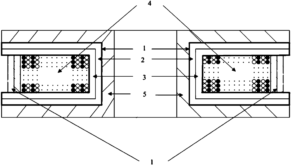
[0020] like figure 1 Said, the present invention provides a kind of optical fiber sensing coil assembly, comprises the bobbin of one side opening and the optical fiber sensing coil that is arranged in the bobbin, and the composite armor structure that is arranged between the sensing coil of optical fiber and bobbin ; The composite armor structure is a multi-layer (2 or more) structure with good thermal conductivity layers and heat insulation layers alternated.

[0021] The surface of the optical fiber sensing coil at the opening of the coil frame is also provided with a composite armor structure.

[0022] The good thermal conductivity layer is bonded to the coil frame, and the heat insulation lay...


PUM


Abstract

The invention discloses an optical fiber sensing coil component and an optical fiber gyro with the same. The optical fiber sensing coil component comprises a coil framework, an optical fiber sensing coil and a combined armor structure. An opening is formed in one side of the coil framework. The optical fiber sensing coil is arranged in the coil framework. The combined armor structure is arranged between the optical fiber sensing coil and the coil framework, and is of a multilayer structure formed by alternate stacking of high-heat-conducting layers and heat-insulating layers. The optical fibersensing oil component and the optical fiber gyro with the same have the advantages that temperature distribution uniformity and temperature change rate in the optical fiber sensing coil are improvedremarkably, and Shupe effect nonreciprocal phase shifting caused by time-varying environment temperatures is reduced effectively.

Description

technical field [0001] The invention relates to the technical field of optical fiber sensing coils, in particular to an optical fiber sensing coil assembly and an optical fiber gyroscope with the assembly. Background technique [0002] The interferometric fiber optic gyroscope is a sensor that detects the angular velocity of the carrier based on the Sagnac effect. When the angular velocity of the carrier in the inertial coordinate system is not equal to 0, the clockwise (clockwise, CW) and There is a phase difference proportional to the angular rate between counter-clockwise (counter-clockwise, CCW) lights, and the angular rate signal is converted into an output light intensity signal through the interference between the CW and CCW lights. Interferometric fiber optic gyroscopes overcome a series of shortcomings of electromechanical gyroscopes and laser gyroscopes. They have the advantages of all solid state, high reliability, large dynamic range, wide frequency band, small s...

Claims


Application Information

Patent Timeline
Patent Type & Authority Applications(China)
IPC IPC(8): G01C19/72
CPCG01C19/72
Inventor 傅长松胡宗福姜辉陈上碧
Owner SHANGHAI XIN YUE LIAN HUI ELECTRONICS TECH
Learn More