Plasma processing apparatus

a processing apparatus and plasma technology, applied in the field of plasma processing apparatus, can solve the problems of direct expansion type temperature control unit for electrostatic adsorption electrode, limited refrigerant temperature control range, and inability to compress refrigerant, etc., to achieve high heat input, high wafer bias power, and high heat input

Active Publication Date: 2008-11-27
HITACHI HIGH-TECH CORP
View PDF23 Cites 213 Cited by
  • Summary
  • Abstract
  • Description
  • Claims
  • Application Information

AI Technical Summary

Benefits of technology

[0017]One feature of the present invention makes it possible to provide a temperature control unit for an electrostatic adsorption electrode that is capable of controlling the wafer temperature over a wide temperature range while high heat input etching is conducted with high wafer bias power applied.
[0018]Another feature of the present invention makes it possible to provide a plasma processing apparatus having a temperature control unit for an electrostatic adsorption electrode that is capable of controlling the wafer temperature rapidly over a wide temperature range without affecting in-plane uniformity while high heat input etching is conducted with high wafer bias power applied.

Problems solved by technology

However, the expansion valve functions to reduce the refrigerant temperature in the electrostatic adsorption electrode (evaporator) and cannot compress the refrigerant to raise the pressure.
Therefore, it is difficult to adjust the evaporation temperature of the refrigerant in the electrostatic adsorption electrode to a high temperature so that the refrigerant temperature control range is limited to the low-pressure side.
Thus, a direct expansion type temperature control unit for the electrostatic adsorption electrode is at a disadvantage in that its operating temperature range is narrow.
Further, even if the refrigerant can be compressed in the electrostatic adsorption electrode, it is anticipated that the electrostatic adsorption electrode might deform due to a refrigerant pressure rise (thereby affecting the electrostatic adsorption force of the wafer).
Thus, the above method cannot readily adjust the refrigerant evaporation temperature to a high temperature close to a condensation temperature because it cannot easily compress the refrigerant in the electrostatic adsorption electrode.
Thus, the above method cannot readily adjust the refrigerant evaporation temperature to a high temperature close to the condensation temperature because it cannot easily compress the refrigerant in the electrostatic adsorption electrode 1.
Further, no heat source is available except for heat input from plasma during wafer processing.
However, this method cannot control the refrigerant evaporation temperature because the heater cannot control the refrigerant pressure.

Method used


Image

  • Plasma processing apparatus
  • Plasma processing apparatus
  • Plasma processing apparatus

Examples


first embodiment

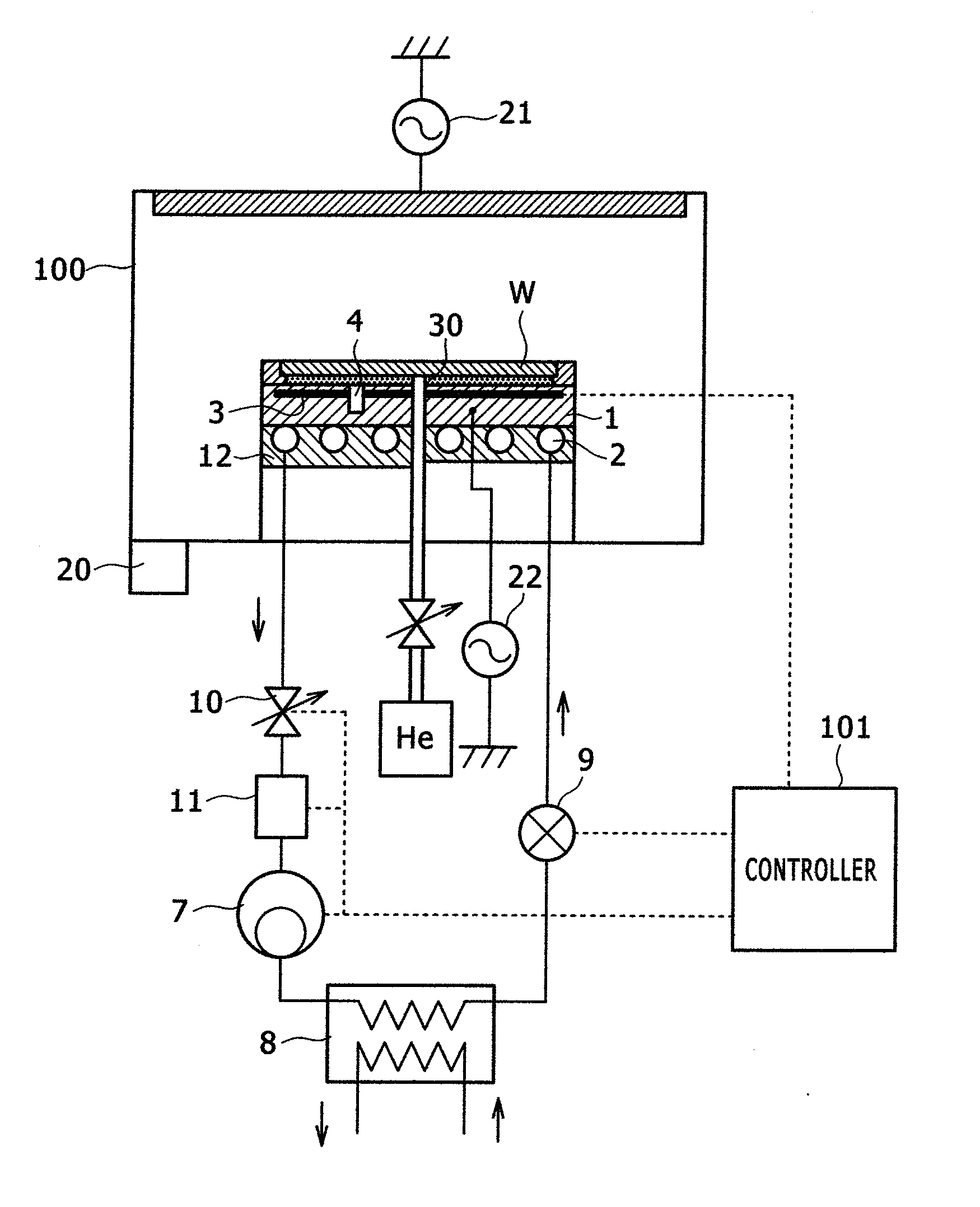
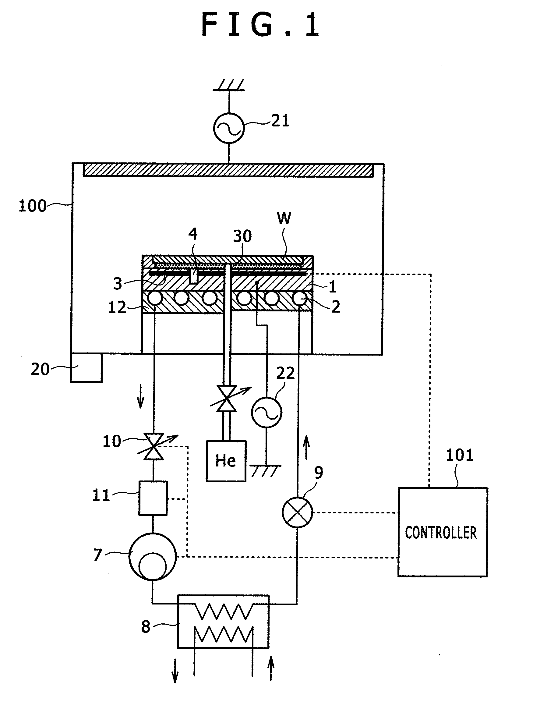
[0039]FIG. 1 is a schematic diagram illustrating the configuration of a plasma processing apparatus having a temperature control unit according to a first embodiment of the present invention. The plasma processing apparatus having a temperature control unit has a processing chamber 100. The processing chamber 100 includes an electrostatic adsorption electrode 1 having an electrostatic adsorption insulation thin film on which a wafer W is to be mounted as a sample; an evacuation system 20 for evacuating the processing chamber 100; an antenna power supply 21 for applying high-frequency power for plasma generation to the processing chamber 100; a process gas supply system (not shown) for supplying a process gas for plasma generation to the processing chamber 100; a bias power supply 22 for applying high-frequency power for biasing to the electrostatic adsorption electrode 1; and a He gas supply system 30 for supplying a heat transfer gas to a gap between the electrostatic adsorption in...

second embodiment

[0047]The plasma processing apparatus having a temperature control unit according to a second embodiment will now be described with reference to FIGS. 3A to 3C, 4A, and 4B. The second embodiment assumes that the plasma processing apparatus is configured as shown in FIG. 1.

[0048]FIGS. 3A to 3C show typical refrigerant pressure control operations according to the present embodiment, and assumes that Pa

[0049]First of all, a control operation performed to adjust the temperature of the electrostatic adsorption electrode 1 to a medium- or low-temperature region will be described with reference to FIG. 3A and FIG. 4A. At first, direct expansion type refrigeration cycle characteristics (a), which are shown in FIG. 3A, will be described. The refrigerant is compressed by the compressor 7 to obtain a high-temperature liquid refrigerant (step 1). The condenser 8 provides air cooling or water ...

third embodiment

[0056]A third embodiment of the present invention will now be described with reference to FIGS. 5A to 5D. The third embodiment is obtained by modifying a thin-walled cylindrical flow path structure of the plasma processing apparatus having a temperature control unit according to the first embodiment. In the direct expansion type refrigeration cycle, the evaporation temperature can be controlled at 1-second intervals by adjusting the refrigerant pressure. When these characteristics are to be used to exercise high-speed control over the wafer temperature, it is necessary to reduce the heat transfer loss between the wafer W and refrigerant flow path 2. In other words, it is necessary to decrease the heat capacity of the electrostatic adsorption electrode 1 on which the wafer W is to be mounted. It is conceivable that the heat capacity of the electrostatic adsorption electrode 1 may be decreased, for instance, by reducing its mass or by changing its constituent material to a low-heat-ca...


PUM

PropertyMeasurementUnit
pressure Pbaaaaaaaaaa
refrigerant temperature Tbaaaaaaaaaa

Abstract

The present invention provides a temperature control unit for an electrostatic adsorption electrode that is capable of controlling the wafer temperature rapidly over a wide temperature range without affecting in-plane uniformity while high heat input etching is conducted with high wafer bias power applied. A refrigerant flow path provided in the electrostatic adsorption electrode serves as an evaporator. The refrigerant flow path is connected to a compressor, a condenser, and a first expansion valve to form a direct expansion type refrigeration cycle. A second expansion valve is installed between the electrostatic adsorption electrode and the compressor to adjust the flow rate of a refrigerant. This makes it possible to compress the refrigerant in the refrigerant flow path of the electrostatic adsorption electrode and adjust the wafer temperature to a high level by raising the refrigerant evaporation temperature. Further, a thin-walled cylindrical refrigerant flow path is employed so that the thin-walled cylinder is deformed only slightly by the refrigerant pressure.

Description

CLAIM OF PRIORITY[0001]The present invention application claims priority from Japanese application JP2007-136870 filed on May 23, 2007, the content of which is hereby incorporated by reference into this application.BACKGROUND OF THE INVENTION[0002](1) Field of the Invention[0003]The present invention relates to a plasma processing apparatus that provides microfabrication in a semiconductor manufacturing process, and more particularly to a plasma processing apparatus having a temperature control unit for exercising temperature control over an electrode section that retains and locks a semiconductor wafer.[0004](2) Description of the Related Art[0005]Temperature management of a currently processed wafer is important when a plasma processing apparatus processes the micropattern of a wafer surface with high precision. If the wafer surface temperature can be optimally controlled in accordance with the progress of a process, it is possible to not only increase processing accuracy but also...

Claims


Application Information

Patent Timeline
Patent Type & Authority Applications(United States)
IPC IPC(8): H01L23/34H01L21/306
CPCH01J37/32431H01J2237/2001H01L21/67109H01L21/6831H01L2924/0002F25B41/062H01L2924/00F25B41/34Y02B30/70C23C16/463
Inventor TANDOU, TAKUMIYOKOGAWA, KENETSUIZAWA, MASARU
Owner HITACHI HIGH-TECH CORP
Why Eureka
Try Eureka