
Static inclination test bench control system

A technology of control system and tilt test, which is applied in the field of machinery, can solve problems such as complex control, and achieve the effects of meeting robustness requirements, reducing electromagnetic noise, and improving stiffness

Inactive Publication Date: 2018-03-13
许亚夫
View PDF0 Cites 2 Cited by
  • Summary
  • Abstract
  • Description
  • Claims
  • Application Information

AI Technical Summary

Problems solved by technology

However, due to the diversity of the solutions of the parallel mechanism, the control is relatively complicated, and the positional relationship between the input and output components of the mechanism must be solved

Method used


Image

  • Static inclination test bench control system
  • Static inclination test bench control system

Examples


Embodiment Construction

[0013] The present invention will be further described below in conjunction with drawings and embodiments.

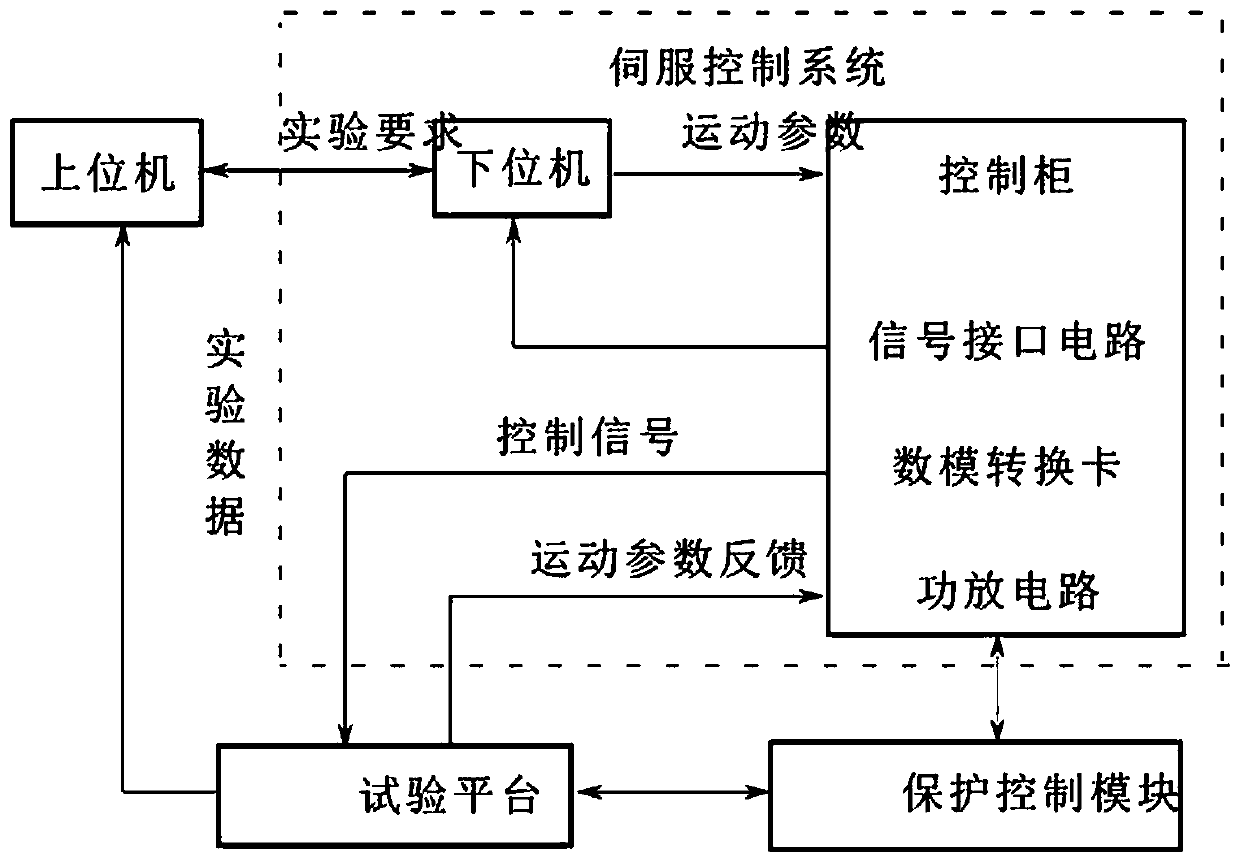
[0014] Such as figure 1 , The control system of the tilting test bench consists of two parts: mechanical and electrical control. Considering the volume and weight of the load, the mechanical part uses the hydraulic cylinder as the main driving device.

[0015] The electrical control part includes upper computer, lower computer, protection control circuit, data acquisition unit, etc.

[0016] To design a control system, we must first consider the input signal of the system, that is, the final control quantity of the system. For a tilting test bench system, the input signal is the tilt angle of the bench top. However, the actual physical system is a mechanical structure of seven linkages, and the platform structure is composed of a platform, a foundation, a hydraulic cylinder, tie rods and a spherical joint. The hydraulic cylinder is connected between the upper platfo...


PUM


Abstract

A static tilting test bench control system is composed of mechanical and electrical control parts. The control system adopts a double-closed-loop composite control structure for the position of the oil cylinder piston and the pressure difference between the upper and lower chambers, and adopts a double-closed-loop composite control structure, which improves the servo stiffness of the system and enhances the system's suppression of interference. On the premise of meeting the requirements of static precision, the control system effectively limits the influence of electrical noise and hydraulic pulsation, meets the requirements of angle error, and the platform is in good condition.

Description

Technical field [0001] The invention relates to a control system of a static inclined test bench, which is suitable for the mechanical field. Background technique [0002] The inclined test bench is mainly used to test the performance indicators of the engine under various inclinations of simulated real road slopes, and provides an important data basis for the design and finalization of the engine. The inclined test bench developed by the author mainly works in a stable state. After the test bench is tilted to the command angle, the engine test is carried out under the load condition, so it is called a static inclined test bench. The inclination angles are x axis direction ±30° and y The axial direction is ±35°, and there is basically no coupling between the two axial rotation angles. [0003] The parallel structure was first proposed by D.Stewart in 1965. Compared with the serial structure, the kinematic structure has advantages. However, due to the diversity of the so...

Claims


Application Information

Patent Timeline
Patent Type & Authority Applications(China)
IPC IPC(8): G01M15/02
CPCG01M15/02
Inventor 许亚夫
Owner 许亚夫
Learn More