
Three-sided five-wire machine tool space geometry error measurement and identification method based on plane grating

A planar grating and geometric error technology, applied in the direction of measuring devices, optical devices, instruments, etc., can solve the problems of sensitive installation of measuring equipment, increased measurement errors, mutual covering, etc.

Active Publication Date: 2018-03-16
XI AN JIAOTONG UNIV
View PDF15 Cites 12 Cited by
  • Summary
  • Abstract
  • Description
  • Claims
  • Application Information

AI Technical Summary

Problems solved by technology

The multi-line method based on laser interferometer includes nine-line method, fourteen-line method, etc. These methods need to use interferometer to measure the error of multiple specific straight lines in space, there are some shortcomings in measurement efficiency, and at the same time, the possibility of measurement error is increased The method of step-by-step body diagonals obtains the spatial geometric error value by measuring and identifying the four body diagonals of the machine tool measurement space. This method is very sensitive to the installation of measuring equipment, and the identification results obtained by this method alone are unreliable. However, there is a possibility of mutual concealment between errors; the step-by-step identification method uses planar gratings to measure multiple different trajectories on different planes, and uses different trajectories to independently identify various errors; these phenomena show that the existing spatial geometric error identification methods are still There are some deficiencies in measurement efficiency and measurement accuracy

Method used


Image

  • Three-sided five-wire machine tool space geometry error measurement and identification method based on plane grating
  • Three-sided five-wire machine tool space geometry error measurement and identification method based on plane grating
  • Three-sided five-wire machine tool space geometry error measurement and identification method based on plane grating

Examples


Embodiment Construction

[0056] The present invention will be described in further detail in conjunction with the accompanying drawings.

[0057] A method for measuring and identifying spatial geometric errors of a three-sided five-line machine tool based on planar gratings, comprising the following steps:

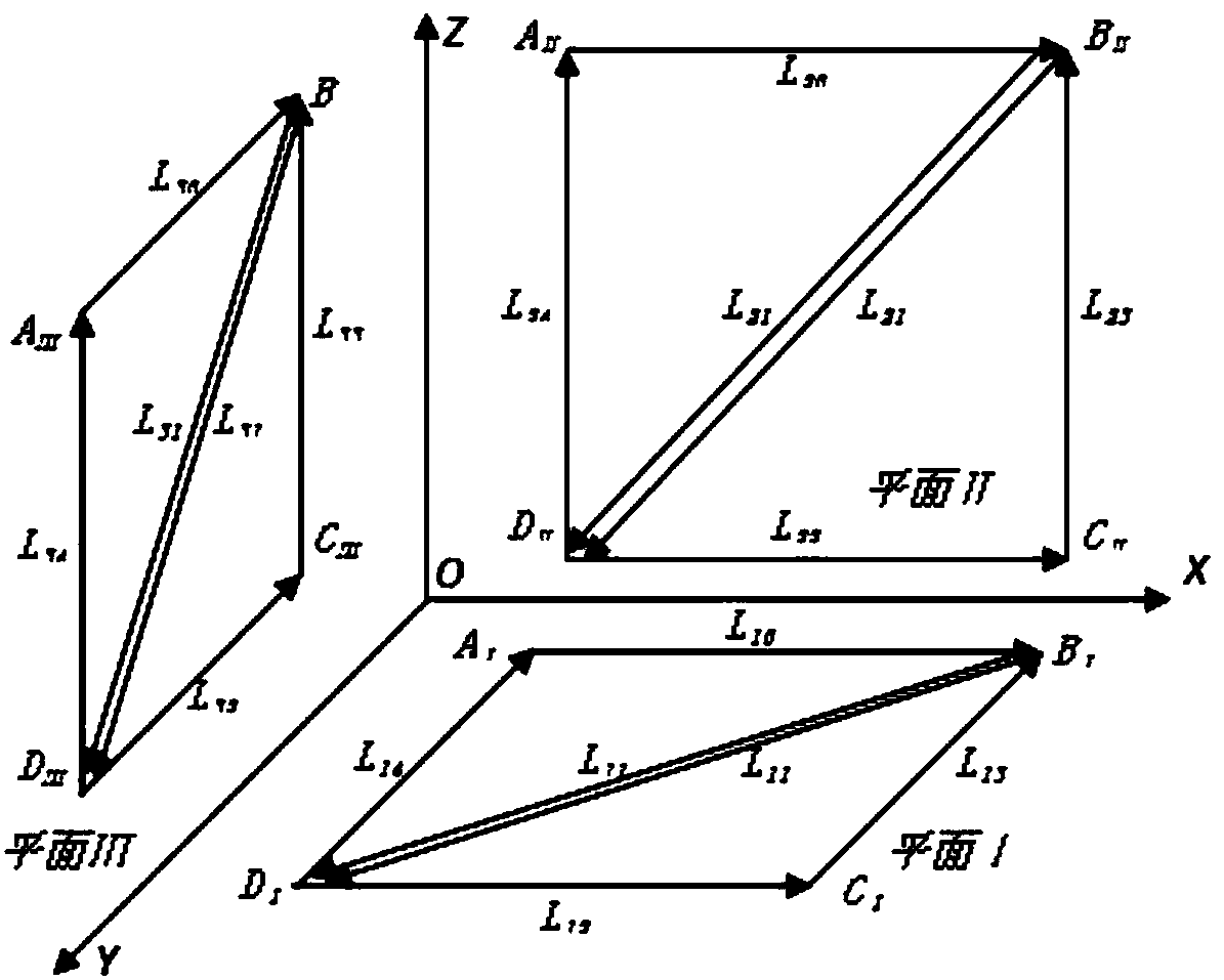
[0058] 1) Refer to figure 1 , in the three measurement planes XOY, XOZ, YOZ, design and plan the measurement path within the measurement range of the planar grating;

[0059] For the XOY plane I, define the measurement path within the measurement range of the plane grating, and the end point of the path is A Ⅰ (x 10 ,y 10 ,z 0 ), B Ⅰ (x 11 ,y 10 ,z 0 ), C Ⅰ (x 11 ,y 11 ,z 0 ), D Ⅰ (x 10 ,y 11 ,z 0 ); from A Ⅰ along L 10 Exercise to B Ⅰ , from B Ⅰ along L 11 Exercise to D Ⅰ , from D Ⅰ along L 12 Movement to C Ⅰ , from C Ⅰ along L 13 Exercise to B Ⅰ , from B Ⅰ along L 11 Exercise to D Ⅰ , and finally from D Ⅰ along L 14 Movement to A Ⅰ ;

[0060] In the same way, t...


PUM


Abstract

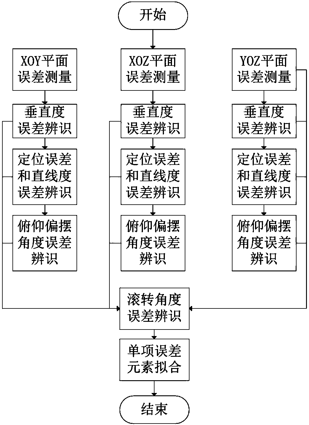
The invention provides a three-sided five-wire machine tool space geometry error measurement and identification method based on plane grating. The method is characterized by designing and planning measurement paths in a measurement range of the plane grating in three measurement planes of XOY, XOZ and YOZ respectively; then, carrying out identification on each error in the planes of XOY, XOZ and YOZ in sequence: to begin with, carrying out identification to obtain a perpendicularity error between two axle in one measurement plane, carrying out identification based on relationship between different trajectories to obtain pitching and deflection angle errors after eliminating the influence of the perpendicularity error, carrying out identification to obtain positioning errors and straightness errors after eliminating the influence of the angle errors, and finally, substituting the obtained errors obtained through identification of the three planes to models and carrying out identification to obtain roll angle errors; and carrying out parameterized modeling on each geometric error term, obtaining an error curve of each geometric error through an orthogonal polynomial fitting method, and finally, realizing a full identification process of the space geometry errors. The method can meet space geometry error identification requirements, and has the advantages of high measurement efficiency and high measurement precision.

Description

technical field [0001] The invention belongs to the technical field of machining accuracy of numerical control machine tools, and in particular relates to a method for measuring and identifying spatial geometric errors of a three-sided five-line machine tool based on a plane grating. Background technique [0002] The original geometric error of the machine tool and the thermal error in the machining process seriously affect the machining accuracy of the machine tool. Among them, the geometric error and thermal error account for 40% to 70% of the total error. Therefore, solving the geometric error is the key to improving the accuracy of the CNC machine tool. Key technologies are of great significance. Geometric errors are mainly caused by the shape and position accuracy of the CNC machine tool parts themselves and the assembly errors generated during the assembly process, and are reflected on the moving parts with the movement of the machine tool, thereby affecting the machin...

Claims


Application Information

Patent Timeline
IPC IPC(8): G01B11/00
CPCG01B11/002
Inventor 姜歌东赵鹏巍陶涛郭世杰
Owner XI AN JIAOTONG UNIV
Learn More