Secondary cell charging method

A technology of secondary battery and charging method, which is applied in secondary battery charging/discharging, secondary battery, secondary battery repair/maintenance, etc., and can solve the problem of limited service life of battery cells, shortened charging time, and inability to fully charge batteries, etc. problem, to achieve the effect of prolonging the service life, reducing the time of high-voltage charging, and increasing the charging speed

Inactive Publication Date: 2018-03-16
NINGDE AMPEREX TECH
View PDF5 Cites 14 Cited by
  • Summary
  • Abstract
  • Description
  • Claims
  • Application Information

AI Technical Summary

Problems solved by technology

One of the high-current constant-current charging methods has a charging termination voltage greater than the known charging limit voltage, thereby shortening the charging time, but in some cases the battery cannot be fully charged, and the range of use is limited.
Another constant current charging method increases the charging speed by increasing the limiting voltage of constant current charging, but it is difficult to control whether the charging capacity is consistent with the rated capacity of the battery cell, and it is prone to the p

Method used


Image

  • Secondary cell charging method
  • Secondary cell charging method
  • Secondary cell charging method

Examples


Embodiment 1

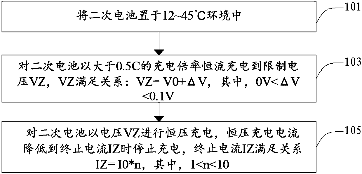
[0033] Step 201, placing the manufactured secondary battery in a constant temperature environment of 45°C.

[0034] The anode of the secondary battery is graphite, and the cathode is lithium cobalt oxide. At 25°C, the fully charged rated charging capacity of the secondary battery Q 0 3730mAh, fully charged cut-off voltage V 0 is 4.45V.

[0035] Step 203, charge the secondary battery with a constant current at a charge rate of 1.5C to a limit voltage of 4.48V.

[0036] Step 205, charge the secondary battery with a constant voltage of 4.48V to a termination current of 0.746A, and stop charging.

Embodiment 2

[0045] Step 301, placing the fabricated secondary battery in a constant temperature environment of 25°C.

[0046] The anode of the secondary battery is graphite, and the cathode is lithium cobalt oxide. At 25°C, the fully charged rated charging capacity of the secondary battery Q 0 3500mAh, fully charged cut-off voltage V 0 is 4.40V.

[0047] Step 303, charge the secondary battery with a constant current at a charge rate of 2C to a limit voltage of 4.45V.

[0048] Step 305, charge the secondary battery with a constant voltage of 4.45V to a termination current of 0.81A, and stop charging.

Embodiment 3

[0054] Step 401, placing the manufactured secondary battery in a constant temperature environment of 25°C.

[0055] The anode of the secondary battery is graphite, and the cathode is lithium iron phosphate. At 25°C, the fully charged rated charging capacity of the secondary battery Q 0 1850mAh, fully charged cut-off voltage V 0 It is 3.70V (the known constant current charging limit voltage V of this battery system 0 3.6 ~ 3.8V).

[0056] Step 403, charge the secondary battery with a constant current at a charge rate of 3C to a limit voltage of 3.80V.

[0057] Step 405, charge the secondary battery with a constant voltage of 3.80V to a termination current of 0.63A, and stop charging.


PUM


Abstract

The invention discloses a secondary cell charging method. The method is characterized in that a secondary cell is subjected to constant-current charging to limiting voltage VZ, wherein VZ is larger than the widely known constant-current charging limiting voltage V0; the secondary cell is subjected to the constant-voltage charging according to the voltage VZ, and charging stops when the constant-voltage charging current is reduced to termination current IZ, wherein the termination current IZ is larger than the widely known constant-voltage charging termination current I0. Compared with the prior art, the secondary cell charging method is characterized in that in a constant-current constant-voltage charging method, certain constant current charging limiting voltage and the constant-voltage charging termination current are set, high-voltage charging time during a cell charging process is reduced, under prerequisite that battery capacity does not loss, the charging speed of the cell is increased, and the usage life of the cell is effectively prolonged.

Description

technical field [0001] The invention belongs to the field of secondary batteries, and more specifically, the invention relates to a method for charging a secondary battery. Background technique [0002] Lithium-ion batteries or polymer lithium-ion batteries have a known charging limit voltage when charging, and the charging is carried out in a constant current and constant voltage mode, that is: first charge with a constant current, and then change to a known charging limit voltage when charging to a known charging limit voltage. Charging limit voltage constant voltage charging, at this time the charging current gradually decreases, when it decreases to 0.01C ~ 0.05C, stop charging. In the constant current charging stage, the voltage at both ends of the battery is composed of two parts, one is the stable voltage between the positive and negative electrodes of the battery, and the other is the voltage difference caused by ohmic internal resistance, concentration polarization ...

Claims


Application Information

Patent Timeline
IPC IPC(8): H01M10/44
CPCH01M10/44H01M10/446Y02E60/10
Inventor 高潮骆福平方占召曾巧余红明龚美丽
Owner NINGDE AMPEREX TECH
Why Eureka
Try Eureka