Eureka AIR delivers breakthrough ideas for toughest innovation challenges, trusted by R&D personnel around the world.

Novel single-phase cylindrical transverse flux switched reluctance linear motor

A technology of transverse magnetic flux and switched reluctance, applied in electrical components, electromechanical devices, electric components, etc., can solve the problems of low motor output volume ratio, reduce motor output volume ratio, and increase motor eddy current loss, etc. The effect of engineering application value, small eddy current loss and large average output

Inactive Publication Date: 2018-03-16
CHINA UNIV OF MINING & TECH
View PDF2 Cites 4 Cited by
  • Summary
  • Abstract
  • Description
  • Claims
  • Application Information

AI Technical Summary

Problems solved by technology

In the traditional longitudinal flux cylindrical switched reluctance linear motor, because part of the magnetic flux direction is parallel to the motor shaft, the eddy current loss of the motor is increased. In addition, due to the large magnetic flux leakage in the stator mover slot, the electromagnetic output of the motor is less saturated. Faster, reducing the output volume ratio of the motor
However, the existing transverse flux cylindrical switched reluctance linear motor lacks the optimization of the relationship between different number of poles and the average output, which may lead to a low ratio of motor output to volume

Method used


Image

  • Novel single-phase cylindrical transverse flux switched reluctance linear motor
  • Novel single-phase cylindrical transverse flux switched reluctance linear motor
  • Novel single-phase cylindrical transverse flux switched reluctance linear motor

Examples


Embodiment Construction

[0021] An embodiment of the present invention will be further described below in conjunction with accompanying drawing:

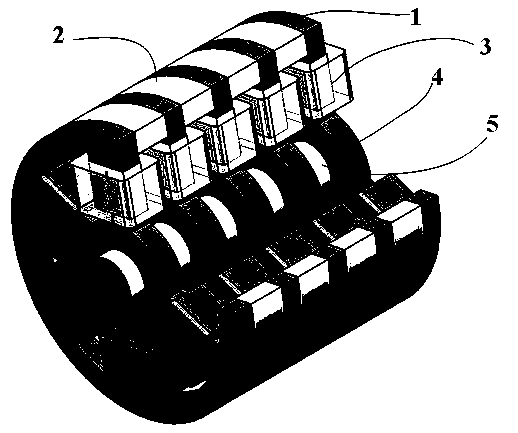
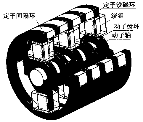
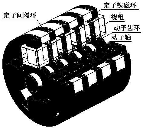
[0022] The novel single-phase cylindrical transverse flux switched reluctance linear motor of this embodiment is composed of a stator ferromagnetic ring, a stator spacer ring, a stator winding, a mover gear ring, and a mover shaft. The ferromagnetic rings of the stator and the spacer rings of the stator are arranged alternately, the gear rings of the mover are sleeved on the shaft of the mover, and the interval between adjacent stator rings is the same as that of the mover rings; two adjacent stator windings in the circumferential direction The direction of winding is opposite; all windings in the longitudinal direction are wound in the same direction. There are 2n teeth in the circumferential direction, and n is the number of pole pairs; the angle between two adjacent teeth is staggered by 360° / 2n.

[0023] In this implementation case, a new type of singl...


PUM


Abstract

The invention discloses a novel single-phase cylindrical transverse flux switched reluctance linear motor, and belongs to the field of novel motor design. The motor is composed of stator ferromagneticrings, stator spacing rings, stator windings, rotor tooth rings and a rotor shaft. The stator ferromagnetic rings and the stator spacing rings are arranged in an alternate way in turn. The winding directions of the two adjacent stator windings in the circumferential direction are opposite. All the windings are connected in series and a magnetic field of NSNSNS poles is formed by the motor. Thereare 2n teeth in the circumferential direction, wherein n is the number of pole pairs and the two adjacent teeth are staggered for the angle of 360 / 2n degrees in turn. According to the motor, the problem of eddy current loss because of the fact that the flux path is parallel to the axial direction of the motor of the conventional longitudinal flux switched reluctance linear motor and the problem ofoptimal average electromagnetic force of the present cylindrical transverse switched reluctance motor under different number of stator poles can be solved. The flux of the motor is transverse flux sothat the eddy current loss is low; meanwhile, the motor has the advantages of large average output, simple structure and high reliability so as to have important engineering value and wide application prospect.

Description

technical field [0001] The invention relates to the field of novel motor design, in particular to a switched reluctance linear motor. Background technique [0002] Linear motors have been increasingly used in magnetic levitation systems, direct drive systems, military and other fields. Among them, the switched reluctance linear motor has attracted more and more attention due to its inherent advantages such as simple structure, firmness, durability, no permanent magnet material, and concentrated winding of the stator. The inherent structure of the traditional unilateral switched reluctance linear motor causes a large normal force to generate a large friction force between the mover and the track, shortening the service life of the motor. Bilateral switched reluctance linear motors can alleviate this problem by virtue of their symmetrical stator structure, but as long as there are irregular bilateral air gaps caused by manufacturing and assembly processes, the normal force ca...

Claims


Application Information

Patent Timeline
Patent Type & Authority Applications(China)
IPC IPC(8): H02K41/03
CPCH02K41/03H02K2213/03
Inventor 陈昊聂瑞
Owner CHINA UNIV OF MINING & TECH
Why Eureka
Eureka Blog
Learn More