Buck-boost LED driving circuit

A technology for driving circuits and lighting circuits, which is applied in the direction of electric light sources, electrical components, electroluminescent light sources, etc., can solve the problems of high switching frequency switching loss, lower system conversion efficiency, etc., reduce power consumption, simplify peripheral applications, Effect of system cost reduction

Pending Publication Date: 2018-03-16
无锡恒芯微科技有限公司
View PDF20 Cites 9 Cited by
  • Summary
  • Abstract
  • Description
  • Claims
  • Application Information

AI Technical Summary

Problems solved by technology

If the driving power supply works in hard switching mode, the increase of its switching frequency will generate a large switching loss, which reduces the conversion efficiency of the system

Method used


Image

  • Buck-boost LED driving circuit
  • Buck-boost LED driving circuit
  • Buck-boost LED driving circuit

Examples


Embodiment Construction

[0025] The specific implementation manners of the present invention will be described in detail below in conjunction with the accompanying drawings.

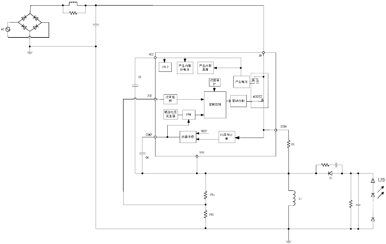
[0026] Such as figure 1 As shown, in the Buck-boost LED drive circuit of the present invention, the applicable lighting circuit includes an inductor L1, LED, capacitor and freewheeling diode D1, the capacitor is arranged at both ends of the LED light group, one end of the capacitor is connected to the inductor, and the other end A freewheeling diode D1 is set between the inductor and the inductor.

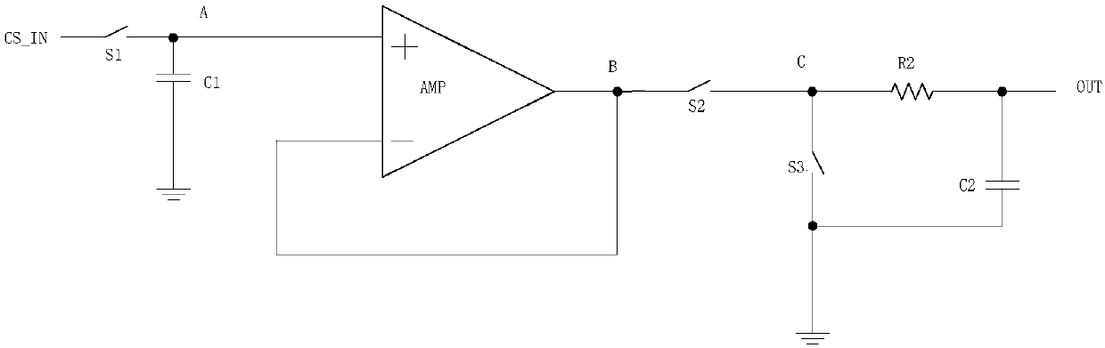
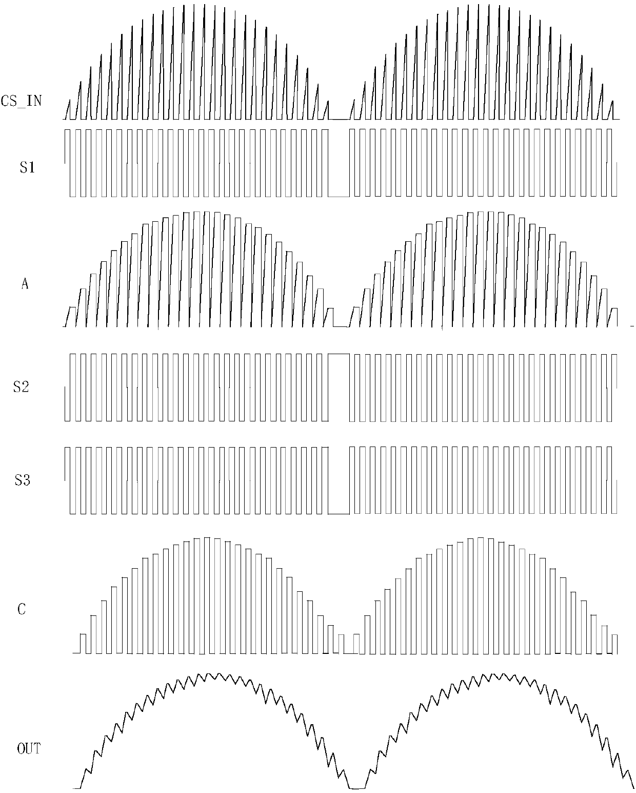
[0027] The drive circuit includes a high-voltage MOSFET tube, a JFET tube, a voltage generation module, a drive control module and a logic control module, a sampling resistor RS, a CS sampling calculation module, an internal compensation module, a sawtooth voltage generator, and a zero-crossing detection module.

[0028] Among them, the drain of the JFET tube is connected to the DC power supply, the drain of the high-voltage MOSFET ...


PUM


Abstract

The invention discloses a Buck-boost LED driving circuit. An applicable lighting circuit comprises an inductor L1, an LED, a capacitor and a fly-wheel diode D1. The driving circuit includes high-voltage MOSFET and JFET tubes, a voltage producing module for producing voltage required for the work of modules in a producing system, a drive control module, a logic control module, a sampling resistor RS, a CS sampling calculation module for calculating equivalent current of the LED in a lighting circuit, an internal compensation module, a sawtooth voltage generator for modulating COMP voltage produced by the internal compensation module and a zero-crossing detection module for detecting wave troughs of an inductor in a resonant mode after demagnetization is completed, wherein the logic controlmodule can opens the high-voltage MOSFET tube when the zero-crossing detection module detects a wave trough signal. The power consumption is reduced, harmonic waves are low, and PFC is improved.

Description

technical field [0001] The invention relates to the technical field of LED driving, in particular to a Buck-boost LED driving circuit. Background technique [0002] With the rapid development of semiconductor technology, the fourth-generation electric light source LED has been widely promoted and used. Compared with traditional electric light sources, LED has many incomparable advantages, such as long life, high efficiency, low power consumption, high brightness, small size, etc., so the application in the field of lighting is particularly prominent. The LED lighting system consists of two parts: LED drive power supply and LED lamps, the core of which is the LED drive power supply. High-efficiency and energy-saving high-power LED drive power has become an important research direction in the industry. [0003] High frequency and miniaturization are an important indicator of switching power supply design. If the driving power supply works in the hard switching mode, the inc...

Claims


Application Information

Patent Timeline
Patent Type & Authority Applications(China)
IPC IPC(8): H05B33/08H05B44/00
CPCH05B45/00H05B45/37
Inventor 吴建良顾南昌吴洁
Owner 无锡恒芯微科技有限公司
Why Eureka
Try Eureka