
Liquid crystal lens with focusing plane capable of being scanned and manufacturing method thereof

A liquid crystal lens and focusing plane technology, applied in optics, instruments, nonlinear optics, etc., can solve problems such as high device driving voltage, uneven electric field distribution of liquid crystal lens driving electrodes, and inability to provide two-dimensional images, etc., to achieve dynamic liquid crystal lens , The effect of simple production process

Inactive Publication Date: 2018-03-20
FUZHOU UNIV
View PDF5 Cites 9 Cited by
  • Summary
  • Abstract
  • Description
  • Claims
  • Application Information

AI Technical Summary

Problems solved by technology

[0002] Two-dimensional (Two-dimension, 2D) image information can bring people clear and colorful 2D visual effects, but the real world in which people live is three-dimensional (There-dimension, 3D), and two-dimensional images cannot provide real The depth information or disparity image information of the world cannot meet the needs of human society
The structure of the liquid crystal lens is simple, the focal length can be adjusted under the applied voltage, and the focus plane can be moved by moving the position of the driving electrode; however, the electric field distribution inside the driving electrode of the liquid crystal lens is not uniform, and the driving voltage of the device is high; Because there is a gap between the drive electrodes of the lens, there is a gap when the focus plane moves

Method used


Image

  • Liquid crystal lens with focusing plane capable of being scanned and manufacturing method thereof
  • Liquid crystal lens with focusing plane capable of being scanned and manufacturing method thereof
  • Liquid crystal lens with focusing plane capable of being scanned and manufacturing method thereof

Examples


Embodiment Construction

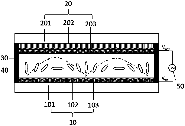
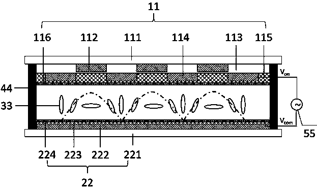
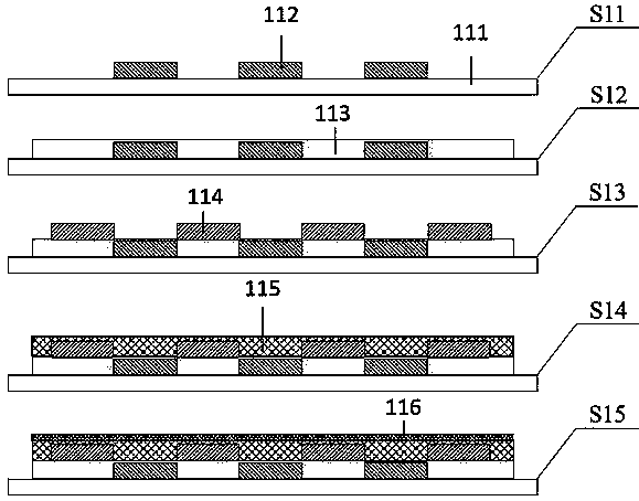
[0037] In order to make the object, technical solution and advantages of the present invention clearer, the present invention will be further described in detail below through specific embodiments and related drawings. In the drawings, the thicknesses of layers and regions are exaggerated for clarity, but should not be considered as strictly reflecting the proportional relationship of geometric dimensions as a schematic diagram. Here, the referenced figures are schematic illustrations of idealized embodiments of the present invention, and the illustrated embodiments of the present invention should not be considered limited to the particular shapes of the regions shown in the figures, but include resulting shapes, such as those caused by manufacturing. deviation. All are represented by rectangles in this embodiment, and the representation in the figure is schematic, but this should not be considered as limiting the scope of the present invention.

[0038]The present invention ...


PUM

PropertyMeasurementUnit
Thicknessaaaaaaaaaa
Thicknessaaaaaaaaaa

Abstract

The invention provides a liquid crystal lens with a focusing plane capable of being scanned and a manufacturing method thereof. The lens includes a first control layer, a second control layer, a liquid crystal layer and a control module; the liquid crystal layer is arranged between the first control layer and the second control layer; the control module is connected with the first control layer and the second control layer separately; the first control layer includes a first transparent base plate, a first driving electrode, a first insulation layer, a second driving electrode, a first alignment layer and a first high-impedance layer; the second control layer includes a second transparent base plate, a third common electrode, a second high-impedance layer and a second alignment layer. Thecraftsmanship of the liquid crystal lens is simple, not only can focal length adjustability of the liquid crystal lens be achieved, but also uniformly-spaced and seamless scanning switch of the focusing plane of the liquid crystal lens can be achieved, and therefore the effect of the dynamic liquid crystal lens is achieved.

Description

technical field [0001] The invention relates to a liquid crystal lens, in particular to a liquid crystal lens with a focus plane scannable and a manufacturing method thereof. Background technique [0002] Two-dimensional (Two-dimension, 2D) image information can bring people clear and colorful 2D visual effects, but the real world in which people live is three-dimensional (There-dimension, 3D), and two-dimensional images cannot provide real The depth information or disparity image information of the world cannot meet the needs of human society. Recreating the real three-dimensional world is the dream of human beings, and it is also the goal pursued by scientific and technological researchers. 3D images can reproduce depth information or parallax image information, which is in line with the human visual habit of observing the objective world. With the continuous development of 3D image information acquisition and display technology, people's reproduction of depth image info...

Claims


Application Information

Patent Timeline
IPC IPC(8): G02F1/29G02B27/22
CPCG02F1/29G02B30/27G02F1/294
Inventor 张永爱郭太良周雄图叶芸林志贤林朝福张桑玲林坚普
Owner FUZHOU UNIV
Learn More