Optical visual vertebral arch pedicle puncture system

A pedicle and optical technology, applied in the field of medical devices, can solve the problems of internal fixation loosening, damage, radiation hazards, etc., and achieve the effect of avoiding puncture

Pending Publication Date: 2018-03-23
SUZHOU INST OF BIOMEDICAL ENG & TECH CHINESE ACADEMY OF SCI
View PDF0 Cites 2 Cited by
  • Summary
  • Abstract
  • Description
  • Claims
  • Application Information

AI Technical Summary

Problems solved by technology

[0004] The traditional pedicle screw placement technology relies on the identification of anatomical landmarks and the experience of the operator. Even experienced spine surgeons may place the screw in a poor position. With the development of pedicle screw internal fixation technology Development and application, in the process of screw placement, the cases of screw piercing through the pedicle frequently occur
[0005] The technique of free-hand screw placement can easily lead to the puncture of the medial cortex of the pedicle. At present, the techniques to improve the accuracy of screw placement mainly include X-ray fluoroscopy and CT navigation, all of which have radiation hazards, and the equipment is expensive.
Among them, CT navigation can easily lead to the penetration of the lateral cortical bone. If the screw penetrates the pedicle cortex, it will not only reduce the strength of the internal fixation and cause loosening of the internal fixation, but may also damage important tissues such as viscera, spinal cord, and nerve roots, leading to more serious injuries. complication

Method used


Image

  • Optical visual vertebral arch pedicle puncture system
  • Optical visual vertebral arch pedicle puncture system
  • Optical visual vertebral arch pedicle puncture system

Examples


Embodiment 1

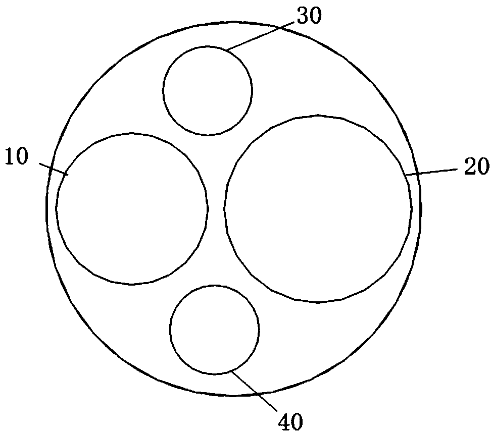
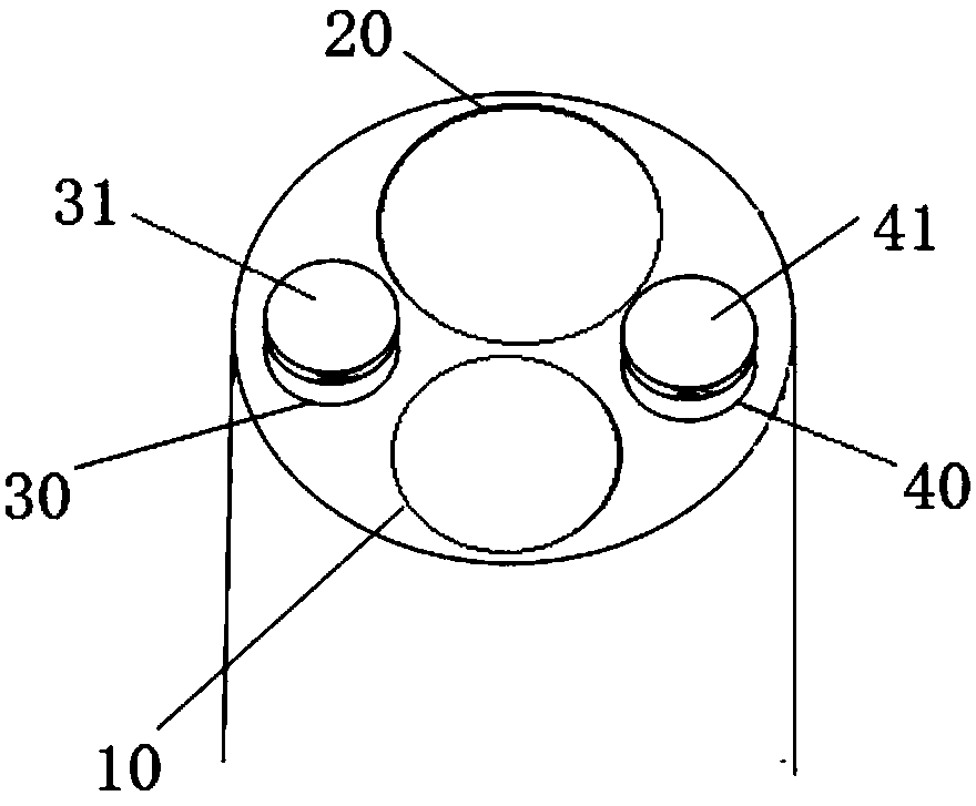
[0031] Such as figure 1 and figure 2 As shown, this embodiment optically visualizes the pedicle puncture system. The puncture system includes a guide needle channel 10 into which a guide needle can be inserted and an illumination imaging channel 20 for placing illumination imaging components. The guide needle channel 10 and illumination imaging The channels 20 are arranged independently of each other. In this embodiment, the guide needle channel 10 is a hollow structure, which can be inserted into the guide needle to realize the positioning during the placement of the pedicle instrument. The illumination imaging channel 20 can realize both illumination and imaging functions, and realize the optical Human eye visualization operation of imaging; this embodiment adopts the principle of optical endoscopic imaging, and places the illumination imaging element in the pedicle puncture system to realize the optical visualization of the process.

[0032] The illumination imaging elem...

Embodiment 2

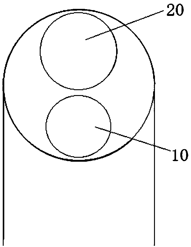
[0040] Such as image 3 As shown, the puncture system described in this embodiment includes a guide needle channel 10 into which a guide needle can be inserted, and an illumination imaging channel 20 for placing illumination imaging components. The guide needle channel 10 and the illumination imaging channel 20 are set independently of each other. In this embodiment, the puncture system does not need to be provided with the water injection channel 30 and the suction channel 40 as described in the first embodiment above.

[0041] In this embodiment, the guide needle channel 10 is a hollow structure, which can be inserted into the guide needle to realize the positioning during the placement of the pedicle instrument. The illumination imaging channel 20 can realize both illumination and imaging functions, and realize the optical Imaging of human eye visualization operations. In this embodiment, the principle of optical endoscopic imaging is adopted, and the illumination imaging ...


PUM

PropertyMeasurementUnit
Diameter sizeaaaaaaaaaa

Abstract

The invention discloses an optical visual vertebral arch pedicle puncture system. The puncture system includes a guide needle channel into which a guide needle can be inserted and a lighting imaging channel for holding a lighting imaging element; and the guide needle channel and the lighting imaging channel are independent of each other. The invention can establish a vertebral arch pedicle channelduring a vertebral arch pedicle screw-setting operation through an optical imaging manner, can avoid cortex breaking of vertebral arch pedicle, and can avoid radiation hazards of X-ray examination and CT navigation adopted by current operations.

Description

technical field [0001] The invention belongs to the field of medical devices, and relates to a medical device used in orthopedic spinal surgery to assist in establishing a pedicle channel, in particular to an optical visualization pedicle puncture system. Background technique [0002] During the surgical treatment of spinal diseases such as thoracolumbar fractures and dislocations, it is necessary to place pedicle instruments (such as pedicle screws) for joint positioning. At present, the application of pedicle instruments combined with bone graft fusion has gradually become the treatment of related orthopedic diseases. gold standard. [0003] The pedicle is the most solid part of the spine and is the effective point of action for surgical manipulation of the spine. However, the pedicles are often adjacent to the spinal cord and nerve roots, especially the inner and lower walls. Any poorly positioned pedicle screws may damage the nerves and cause serious complications. The...

Claims


Application Information

Patent Timeline
IPC IPC(8): A61B17/34A61B17/70A61B17/90A61B90/00A61B34/20
CPCA61B17/3403A61B17/3472A61B17/7074A61B17/88A61B34/20A61B90/361A61B90/37A61B2034/2065A61B2090/3614A61B17/90
Inventor 杨西斌邹俊熊大曦
Owner SUZHOU INST OF BIOMEDICAL ENG & TECH CHINESE ACADEMY OF SCI
Why Eureka
Try Eureka