
Drilling mechanism

A technology of drilling mechanism and seat body, which is applied in the direction of boring/drilling, drilling/drilling equipment, metal processing equipment, etc., which can solve the problems of large space occupation, many parts, and large use limitations, and achieve saving The effect of occupying space, low energy consumption and less consumables

Active Publication Date: 2018-03-23
YANGZHOU HAIXING CNC BRUSH MACHINERY
View PDF7 Cites 16 Cited by
  • Summary
  • Abstract
  • Description
  • Claims
  • Application Information

AI Technical Summary

Problems solved by technology

Such a mechanism is usually arranged in a straight line with the tufting mechanism, and is suitable for the case where one machine head spindle drives multiple drilling mechanisms at the same time. It occupies a large space, has many parts, and has great limitations in use.

Method used


Image

  • Drilling mechanism
  • Drilling mechanism
  • Drilling mechanism

Examples


Embodiment Construction

[0027] In the following description of the present invention, the orientation or positional relationship indicated by the terms "upper", "lower", "front", "rear", "left", "right", "inner", "outer" etc. are based on the attached The orientation or positional relationship shown in the figure is only for the convenience of describing the present invention and simplifying the description, and does not mean that the device must have a specific orientation.

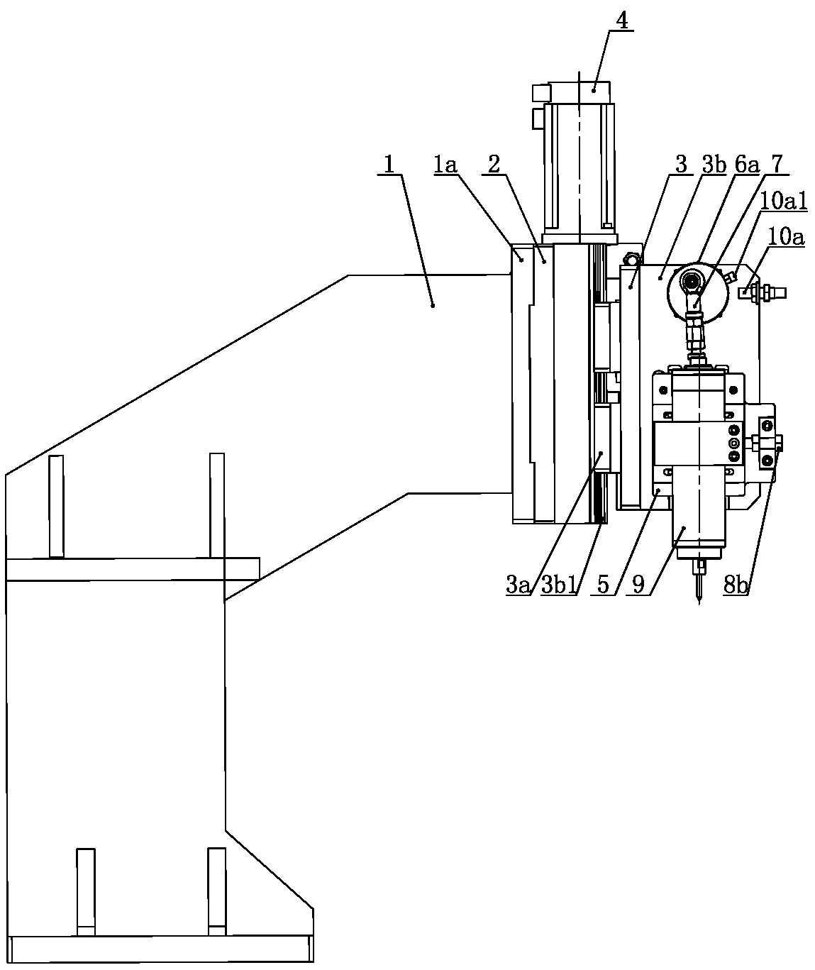
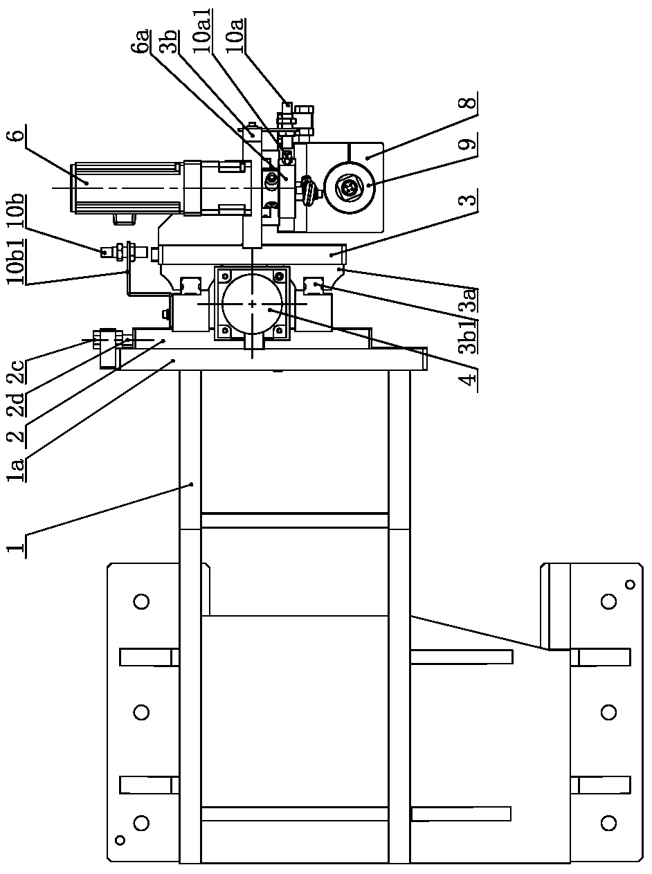
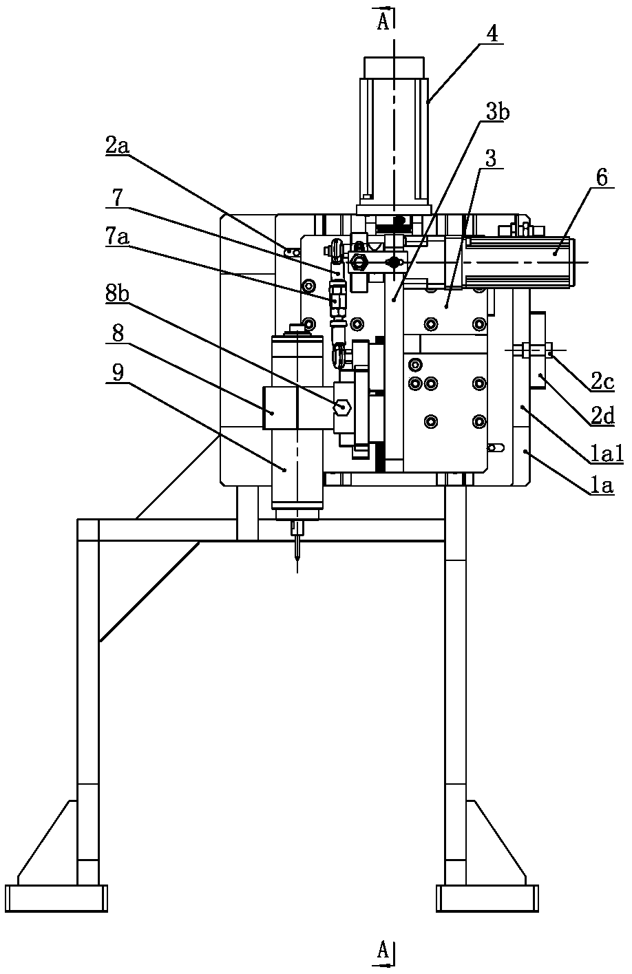
[0028] like Figure 1 to Figure 5 As shown, the drilling mechanism of the present invention comprises a drilling mechanism base 1, the top of the drilling mechanism base 1 is provided with a drilling mechanism base riser 1a with its end facing right, and the drilling mechanism base riser 1a The right side is equipped with a drilling mechanism mounting plate 3b, the drilling mechanism mounting plate 3b is perpendicular to the drilling mechanism seat body vertical plate 1a and extends along the vertical plane, the front end face ...


PUM


Abstract

The invention discloses a drilling mechanism. The drilling mechanism comprises a drilling mechanism seat, wherein a drilling seat vertical plate of which an end surface faces rightwards is arranged onthe upper part of the drilling mechanism seat; a drilling mechanism mounting plate is mounted on the right side of the drilling mechanism seat vertical plate, is perpendicular to the drilling mechanism seat vertical plate and extends along a vertical plane; a drilling sliding plate guide track which extends in the vertical direction is mounted on the lower part of the front end surface of the drilling mechanism mounting plate; the drilling sliding plate guide track is connected with a drilling sliding plate through a sliding block; the upper part of the drilling sliding plate is hinged to aconnecting rod; the upper end of the connecting rod is hinged to the periphery of an eccentric wheel; the eccentric wheel is fixedly mounted at an output end of a drilling servo motor; the drilling servo motor is fixedly mounted on the upper part of the drilling mechanism mounting plate; an electric spindle which extends in the vertical direction is mounted on the lower part of the front end surface of the drilling sliding plate through an electric spindle clamping seat; and a drill bit for drilling is mounted at the lower end of the electric spindle. The drilling mechanism can carry out accurate drilling operation independently, is compact in structure and occupies small space.

Description

technical field [0001] The invention relates to a brush manufacturing equipment, in particular to a drilling mechanism capable of drilling holes on a brush body on a plane, an arc or a cylinder, and belongs to the technical field of drilling equipment. Background technique [0002] Hair combs used for perming and hair dyeing usually have a rod-shaped cylindrical structure, and the handle extends along the axis of the brush head. During the manufacturing process, the two ends of the brush body need to be clamped, and holes are drilled on the cylindrical surface of the brush body. The holes are distributed in an array , and then plant hair in each hole, and blank the material after the wool planting is completed. When drilling, it is hoped that the axis of the drill bit is perpendicular to the axis of the brush body. After the bristles are planted, the bristles on the hair comb are evenly distributed radially. The traditional drilling mechanism needs the head spindle driven b...

Claims


Application Information

Patent Timeline
Patent Type & Authority Applications(China)
IPC IPC(8): B23B41/00
CPCB23B41/00Y02P70/10
Inventor 王勇许富恒李嘉
Owner YANGZHOU HAIXING CNC BRUSH MACHINERY
Learn More