Construction site steel pipe rapid and accurate cutting device

A construction site and cutting device technology, applied in the direction of shearing devices, manufacturing tools, metal processing equipment, etc., can solve the problems of low cutting efficiency, low cutting efficiency, environmental pollution, etc., and achieve improved cutting efficiency, improved cutting efficiency, The effect of avoiding environmental pollution

Active Publication Date: 2018-03-23
盛尔建设集团有限公司
View PDF6 Cites 20 Cited by
  • Summary
  • Abstract
  • Description
  • Claims
  • Application Information

AI Technical Summary

Problems solved by technology

[0002] Due to the advantages of hard texture, non-corrosion, high temperature resistance, and high pressure resistance, steel pipes can be used in various environments. Cutting is generally required when steel pipes are processed into target pipe fittings. At present, most of them use electric saws or other cutting tools for manual Cutting, when manual cutting is used, the labor intensity of the cutting personnel is very high, resulting in low cutting efficiency. In addition, manual cutting is difficult to ensure the cutting quality, which will easily lead to the scrapping of steel pipes and increase the processing cost of pipe fittings. There is a lack of a fixing device for steel pipes, and the cutting efficiency is low
[0003] The existing steel pipe cutting device still cuts by manually pushing the steel pipe, resulting in uneven cutting, low cutting efficiency and easy to cause injury to the operator, which has certain potential safety hazards. The existing device does not have the function of dust removal. A large amount of iron dust is produced, which floats in the air or falls to every corner of the construction site, causing great pollution to the environment and seriously affecting the physical and mental health of construction workers, while causing a lot of cleaning work

Method used


Image

  • Construction site steel pipe rapid and accurate cutting device
  • Construction site steel pipe rapid and accurate cutting device
  • Construction site steel pipe rapid and accurate cutting device

Examples


Embodiment Construction

[0018] The following will clearly and completely describe the technical solutions in the embodiments of the present invention with reference to the accompanying drawings in the embodiments of the present invention. Obviously, the described embodiments are only some, not all, embodiments of the present invention. Based on the embodiments of the present invention, all other embodiments obtained by persons of ordinary skill in the art without making creative efforts belong to the protection scope of the present invention.

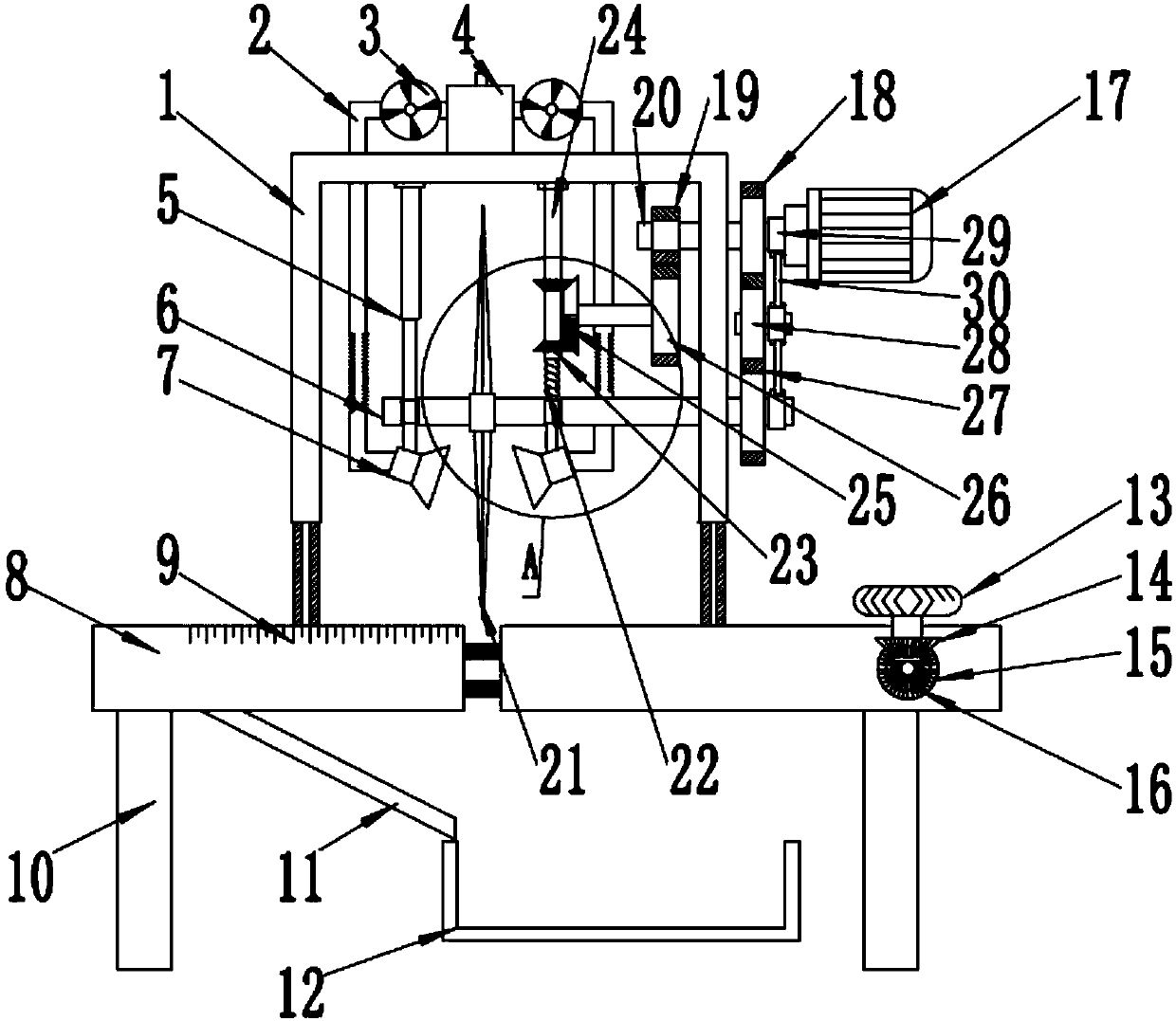
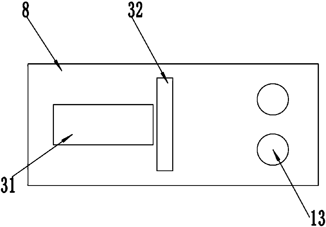
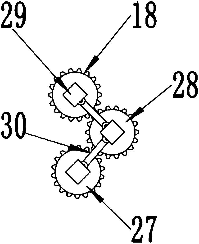
[0019] see Figure 1-4 , a fast and precise cutting device for steel pipes on a construction site, comprising a bracket 1, a workbench 8, a dust removal mechanism, a transmission mechanism, a cutting knife 21, a second motor 17 and a rotating shaft 6; the upper end of the workbench 8 is fixedly mounted with a bracket 1 , the right side of the bracket 1 is provided with a second motor 17, the output end of the second motor 17 is fixedly connected with the secon...


PUM


Abstract

The invention discloses a construction site steel pipe rapid and accurate cutting device. The construction site steel pipe rapid and accurate cutting device comprises a support, a workbench, a dedusting mechanism, a conveying mechanism, a cutting tool, a second motor and a first rotary shaft. The support is fixedly mounted at the upper end of the workbench. The second motor is arranged on the right side of the support. The output end of the second motor is fixedly connected with a second rotary shaft. The lower end of a threaded rod is rotationally connected with the first rotary shaft. The cutting tool is fixedly mounted on the first rotary shaft. The conveying mechanism is arranged on the right side of the workbench and comprises a conveying wheel, a bevel gear A, a bevel gear B and a first motor. The dedusting mechanism is further arranged at the upper end of the support and comprises a gas guide pipe, a suction fan, a magnetic collection groove and a suction hood. The constructionsite steel pipe rapid and accurate cutting device is novel in design and simple in structure, the steel pipe cutting efficiency is greatly improved, meanwhile, the cutting accuracy is improved, the cutting effect is improved, scrap iron can be collected in the cutting process, and environment pollution is effectively avoided.

Description

technical field [0001] The invention relates to the construction field, in particular to a fast and precise cutting device for steel pipes on a construction site. Background technique [0002] Due to the advantages of hard texture, non-corrosion, high temperature resistance, and high pressure resistance, steel pipes can be used in various environments. Cutting is generally required when steel pipes are processed into target pipe fittings. At present, most of them use electric saws or other cutting tools for manual Cutting, when manual cutting is used, the labor intensity of the cutting personnel is very high, resulting in low cutting efficiency. In addition, manual cutting is difficult to ensure the cutting quality, which will easily lead to the scrapping of steel pipes and increase the processing cost of pipe fittings. When the steel pipe lacks a fixing device, the cutting efficiency is low. [0003] The existing steel pipe cutting device still cuts by manually pushing the...

Claims


Application Information

Patent Timeline
Patent Type & Authority Applications(China)
IPC IPC(8): B23D19/00B23Q11/00
CPCB23D19/00B23Q11/0046
Inventor 高军辉
Owner 盛尔建设集团有限公司
Why Eureka
Try Eureka