Preparation method of piezoelectric sensor assembly

A technology of piezoelectric sensors and piezoelectric elements, applied in the direction of using electric/magnetic devices to transmit sensing components, etc., can solve problems such as poor stability, low manufacturing efficiency of piezoelectric sensor components, and unsuitability for large-scale production, and achieve Wide range of effects

Inactive Publication Date: 2018-03-23
XIAMEN NIELL ELECTRONICS
View PDF5 Cites 0 Cited by
  • Summary
  • Abstract
  • Description
  • Claims
  • Application Information

AI Technical Summary

Problems solved by technology

[0004] The assembly made by the above-mentioned method of nut locking and clamping ring can fasten the piezoelectric element 13 and the mass block 14 on the base 10 at one time, because there is a prestress, the mass block 14, the piezoelectric element 13 and the base There is almost no gap between the fixed parts of the seat 10, and at the same time, the mass block 14 and the base 10 are used as conductive electrodes, which can effectively avoid abnormal sensitivity output of the sensor. The application of stress will make the high d 33 and d 15 The performance of the piezoelectric element with a lower value will deteriorate, which will lead to a decrease in sensor sensitivity and poor stability. At the same time, the clamp ring 17 is a very special metal material, which is not suitable for actual large-scale production.
[0005] The assembly made by the method of fixing the piezoelectric element 13 and the mass 14 on the base 10 with epoxy resin and conductive glue requires very skilled operators to operate under a microscope to prevent the process of coating epoxy resin Defects affect the quality of components, and the coating can only be completed in two steps, so the piezoelectric sensor component has low production efficiency and high cost
In addition, epoxy resin and conductive glue are applied, resulting in a large size gap between the mass block, piezoelectric element and the fixed part of the base, which affects the sensitivity output of the sensor, and the sensitivity value is difficult to control, especially due to mass block, piezoelectric element Inconsistent thermal expansion coefficients among components, bases, and organic substances lead to thermal stress, and the use of mass 14 and base 10 as conductive electrodes in components can easily lead to large deviations in sensitivity output

Method used


Image

  • Preparation method of piezoelectric sensor assembly
  • Preparation method of piezoelectric sensor assembly
  • Preparation method of piezoelectric sensor assembly

Examples


Embodiment 1

[0043] A method for preparing a piezoelectric sensor assembly, such as Figure 5 As shown, the specific steps include the following:

[0044] S1. Use the mold to press the low-melting-point tin-brazing powder into tin-brazing rings with dimensions of Φ4.5×4.0×4mm and Φ8.0×7.5×4mm to obtain low-melting-point metal layers in different sizes. 12 and outer low melting point metal layer 18;

[0045] S2. Put the jig 11 of a certain thickness into the bottom of the sleeve rod 102 of the base 10, and the outer diameter of the sleeve rod 102 is Φ4.0mm;

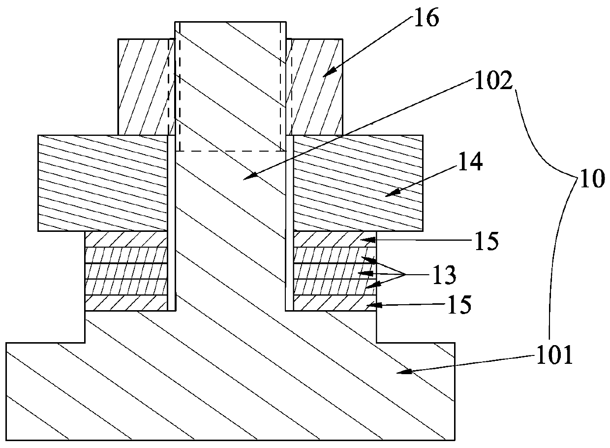
[0046] S3. See Figure 5, put the Φ4.5×4.0×4mm inner low-melting-point metal layer 12, Φ7.5×4.5×4mm piezoelectric element 13, Φ8.0×7.5×4mm outer low-melting-point metal around the sleeve rod 102 on the jig 11 layer 18, and then put the Φ12.5×8.0×5.5mm mass block 14 into the sleeve rod, so that the inner low melting point metal layer 12, the piezoelectric element 13, and the outer low melting point metal layer 18 are sandwiched betwe...

Embodiment 2

[0051] A method for preparing a piezoelectric sensor assembly, such as Image 6 As shown, the specific steps include the following:

[0052] S1. Use a mold to press the low-melting-point tin brazing powder into two square sheets with a size of 4.0×5.0×4.0 mm to obtain a square inner low-melting-point metal layer 12 and an outer low-melting-point metal layer 18;

[0053] S2. Insert the jig 11 of a certain thickness into the bottom of the rod 102 of the base 10;

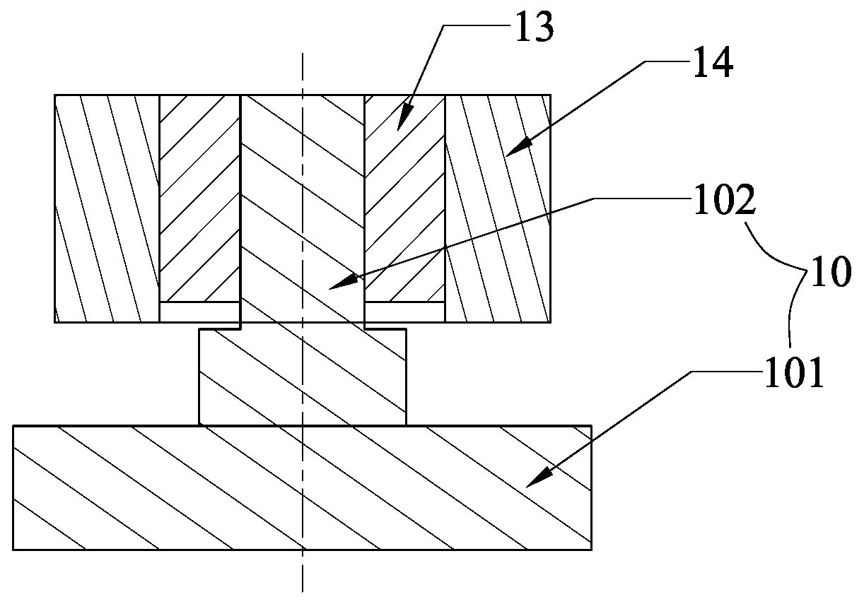
[0054] S3. See Image 6 , put the inner low-melting-point metal layer 12, the piezoelectric element 13, and the outer low-melting-point metal layer 18 in order around the sleeve rod 102 on the jig 11, and then put the mass 14 into the sleeve rod 102, so that the inner low-melting-point metal layer 12 1. The piezoelectric element 13 and the outer low melting point metal layer 18 are sandwiched between the sleeve rod 102 and the mass block 14, and the piezoelectric element 13 is sandwiched between the inner low melting...

Embodiment 3

[0059] A method for preparing a piezoelectric sensor assembly, such as Figure 5 As shown, the specific steps include the following:

[0060] S1. Use a mold to melt the low melting point tin brazing powder and pour it into tin brazing rings with dimensions of Φ4.5×4.0×4mm and Φ8.0×7.5×4mm to obtain a circular inner low melting point metal layer 12 and outer low melting point metal layer 18;

[0061] S2. Put the jig 11 of a certain thickness into the bottom of the sleeve rod 102 of the base 10, and the outer diameter of the sleeve rod 102 is Φ4.0mm;

[0062] S3. See Figure 5 , put the Φ4.5×4.0×4mm inner low-melting-point metal layer 12, Φ7.5×4.5×4mm piezoelectric element 13, Φ8.0×7.5×4mm outer low-melting-point metal around the sleeve rod 102 on the jig 11 layer 18, and then put the Φ12.5×8.0×5.5mm mass block 14 into the sleeve rod, so that the inner low melting point metal layer 12, the piezoelectric element 13, and the outer low melting point metal layer 18 are sandwiched...


PUM

PropertyMeasurementUnit
Melting pointaaaaaaaaaa

Abstract

The invention discloses a preparation method of a piezoelectric sensor assembly. The method comprises the steps that 1) powder of a metal material of a low melting point is pressed by a die or metal of a low melting point is melted and then casted by a die to form interior and exterior low-melting-point metal layers; 2) a metal tool of certain thickness is sleeved with the bottom of a sleeve rod of a pedestal; 3) the interior low-melting-point metal layer, a piezoelectric component and the exterior low-melting-point metal layer are placed surrounding the sleeve rod successively on the tool, and a mass block is sleeved with the sleeve rod; 4) the pedestal, the tool on the pedestal as well as the interior low-melting-point metal layer, the piezoelectric component, the exterior low-melting-point metal layer and the mass block on the tool are placed in an electric furnace or a box type furnace as a whole for insulation; 5) the pedestal, the tool, as well as the interior low-melting-point metal layer, the piezoelectric component, the exterior low-melting-point metal layer and the mass block on the tool are cooled with the furnace or directly taken out and cooled naturally to a temperature lower than the melting point of the metal material; and6) the metal tool is removed from the pedestal, and the required piezoelectric sensor assembly is obtained. According to the invention, the sensor performance is improved, the technical conditions and cost of preparation are lowered, and the production efficiency is improved.

Description

technical field [0001] The invention belongs to the technical field of sensors and transducers, in particular to a method for preparing piezoelectric sensor components used in vibration testing, monitoring and monitoring. Background technique [0002] Piezoelectric sensors work based on the piezoelectric effect of piezoelectric materials. Due to their high sensitivity, wide operating temperature range, and good stability, they have broad applications in the measurement, monitoring, and monitoring of speed, acceleration, pressure, vibration, and shock. application prospects. [0003] At present, the use of piezoelectric sensors mainly adopts nut locking, epoxy resin bonding and clamping rings to install piezoelectric elements and mass blocks on the base, such as figure 1 In the shown positive end compression piezoelectric sensor assembly, a sleeve rod 102 is formed in the middle of the base 10, the piezoelectric element 13 and the mass block 14 are stacked sequentially and p...

Claims


Application Information

Patent Timeline
IPC IPC(8): G01D5/12
CPCG01D5/12
Inventor 王海圣刘瑞林翁新全许静玲
Owner XIAMEN NIELL ELECTRONICS
Why Eureka
Try Eureka