Vertical transition structure

A vertical transition, ground plane technology, used in fixed connections, printed circuit components, electrical components, etc., can solve the problems of not meeting the high-performance transmission requirements of millimeter-wave, poor transmission performance in the millimeter-wave frequency band, and large application limitations, and achieve reliable performance. High performance, wide operating frequency, and the effect of increasing the area of ​​the welding area

Active Publication Date: 2018-03-23
SOUTHWEST CHINA RES INST OF ELECTRONICS EQUIP
View PDF5 Cites 6 Cited by
  • Summary
  • Abstract
  • Description
  • Claims
  • Application Information

AI Technical Summary

Problems solved by technology

However, the contact area between the conductor in the connector and the pad of the vertical transition via is small, and the reliability is poor; in addition, there is a large parallel parasitic plate capacitance between the vertical transition of the stripline and the ground plane of the stripline, which is just in line with the vertical The parasitic series inductance of the transition vias forms an equivalent LC low-pass filter structure, which makes the transmission performance of the millimeter wave frequency band poor, does not meet the high performance transmission requirements of the millimeter wave, and has relatively large application limitations.

Method used


Image

  • Vertical transition structure
  • Vertical transition structure
  • Vertical transition structure

Examples


Embodiment Construction

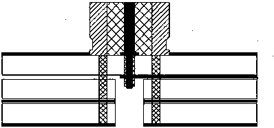
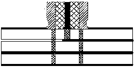
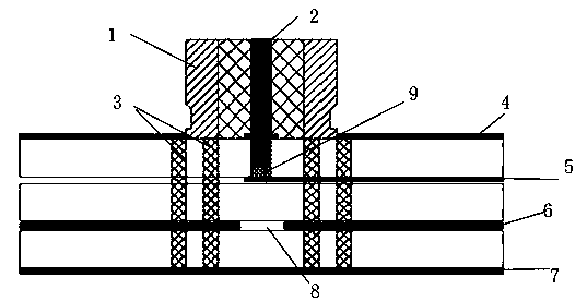
[0017] Such as image 3 Shown is a schematic diagram of the vertical transition structure involved in the present invention. Including radio frequency coaxial connector 1, microwave multilayer printed board.

[0018] The microwave multilayer printed board is respectively a first ground plane 4 , a stripline layer 5 , a second ground plane 6 and a third ground plane 7 from top to bottom.

[0019] A vertical transition blind hole 9 is arranged between the first ground plane 4 and the stripline layer 5; the radio frequency coaxial connector 1 is arranged on the first ground plane 4, and the outer conductor of the radio frequency coaxial connector 1 is connected to the first ground plane 4 Welding to form an electrical connection, where the inner conductor 2 grows appropriately, extends downwards into the vertical transition blind hole 9 and does not exceed the depth of the vertical transition blind hole 9, and welds to form an electrical connection. Since the radio frequency co...


PUM


Abstract

The invention provides a vertical transition structure which comprises a radio frequency coaxial connector and a microwave multilayer printed board. The microwave multilayer printed board is composedof a first grounding plane, a strip line layer, a second grounding plane and a third grounding plane from top to bottom. A vertical transition blind hole is arranged between the first grounding planeand the strip line layer. The radio frequency coaxial connector is arranged on the first grounding plane, and the inner conductor thereof extends downward into the vertical transition blind hole and does not exceed the depth of the vertical transition blind hole. The second grounding plane layer is added with an opening directly facing the area of the vertical transition blind hole. The vertical transition structure provided by the invention has the advantages of full shielding, high reliability and wide working frequency band.

Description

technical field [0001] The invention belongs to the technical field of electronic components, and in particular relates to a design method of a vertical transition structure. Background technique [0002] In recent years, with the continuous development of mobile communication and electronic countermeasures in the direction of miniaturization, low cost, high frequency, and high performance, higher requirements have been put forward for high-performance and high-reliability vertical transition transmission in the microwave and millimeter wave bands. At present, the vertical transition interconnection between the RF coaxial connector and the microwave multilayer printed board in microwave products mainly includes figure 1 , 2 Two ways are shown. [0003] (1) figure 1 The inner conductor of the medium-frequency coaxial connector passes through the vertical transition hole formed by the back-drilling process of the microwave multilayer printed board, and is soldered on the ba...

Claims


Application Information

Patent Timeline
IPC IPC(8): H01R12/58H05K1/02
CPCH01R12/58H05K1/0243
Inventor 舒攀林廖翱周俊笪余生罗洋
Owner SOUTHWEST CHINA RES INST OF ELECTRONICS EQUIP
Why Eureka
Try Eureka