
Variable delay asynchronous time-sequence control circuit and control method

An asynchronous sequence control and variable technology, applied in electrical components, electrical signal transmission systems, analog-to-digital converters, etc., can solve problems such as waiting time, limiting ADC sampling rate, increasing the difficulty of external clock design, etc., to shorten the delay time , reduce waiting time, and increase design difficulty

Active Publication Date: 2018-03-23
XI AN JIAOTONG UNIV
View PDF5 Cites 10 Cited by
  • Summary
  • Abstract
  • Description
  • Claims
  • Application Information

AI Technical Summary

Problems solved by technology

[0003] The control timing of successive approximation analog-to-digital conversion circuits mainly includes synchronous sequential circuits and asynchronous sequential circuits. The cycle of synchronous timing is determined by the longest comparator time plus the largest capacitor settling time, which will limit the sampling rate of the ADC.
In addition, in the current design of high-speed SAR ADC, if synchronous timing is used, an external clock of gigahertz is required, and the clock jitter of the external clock is required to be small enough, which will greatly increase the difficulty of external clock design
[0004] The asynchronous sequential circuit can effectively solve the problems existing in the synchronous sequential circuit. The asynchronous sequential circuit is divided into a comparison phase and a capacitor switching phase during the conversion process, which correspond to the high and low levels of the asynchronous sequential circuit. For example, under the standard 65nm CMOS process, the comparison time of the comparator in the actual circuit is about 200ps, and the switching time of the capacitor is about 2ns, so there is unnecessary waiting time in the asynchronous timing of the traditional structure

Method used


Image

  • Variable delay asynchronous time-sequence control circuit and control method
  • Variable delay asynchronous time-sequence control circuit and control method
  • Variable delay asynchronous time-sequence control circuit and control method

Examples


Embodiment Construction

[0020] The present invention will be further described in detail below in conjunction with the accompanying drawings.

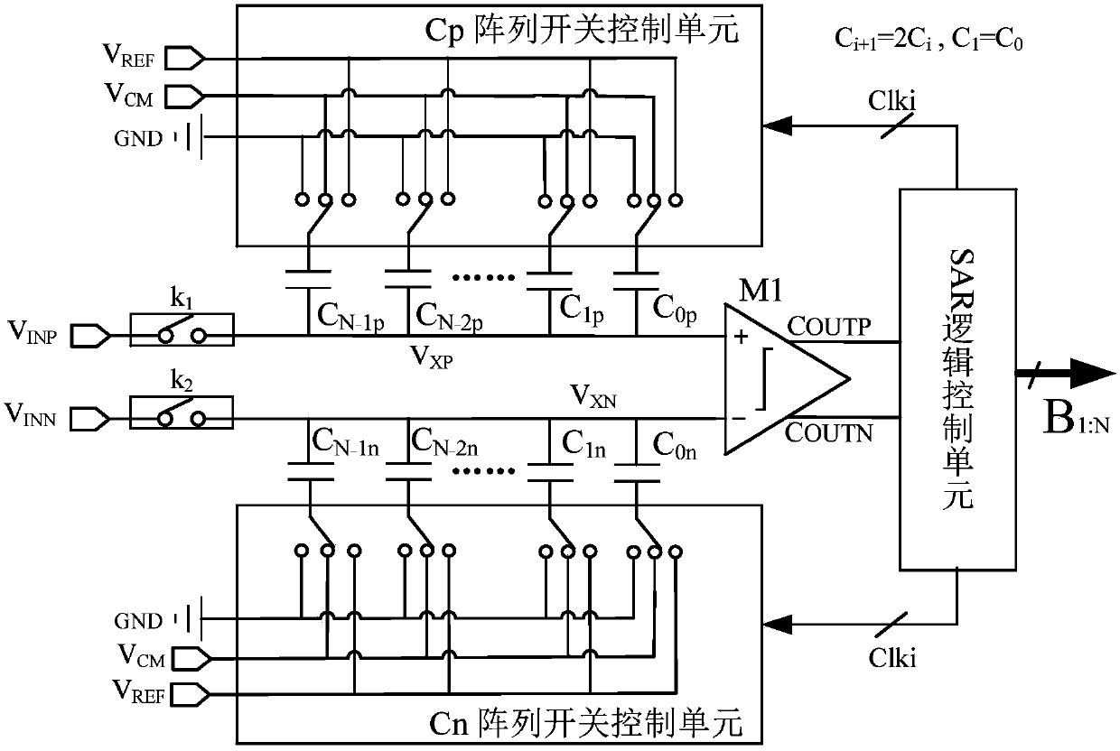
[0021] see figure 1 , the present invention is applied to the variable delay asynchronous sequential control circuit of the successive approximation type analog-to-digital converter including V INP Differential signal input terminal, V INN Differential signal input terminal, V XP Sample and hold circuit, V XN Sample and hold circuit, two-stage dynamic comparator M1, SAR logic control circuit, Cp array switch control unit, Cn array switch control unit, high-level signal terminal V REF , low level signal terminal GND, common mode voltage signal terminal V CM . During the sampling phase, the input signal V INP After sampling switch k 1 Sampling to the upper plate of the positive N-bit DAC binary capacitor array, the input signal V INN After sampling switch k 2 Sampling to the top plate of the negative N-bit DAC binary capacitor array. After sampling, t...


PUM


Abstract

The invention provides a variable delay asynchronous time-sequence control circuit and a control method. The VINP differential signal input end and the VINN differential signal input end of the control circuit are respectively connected with a VXP sampling holding circuit and a VXN sampling holding circuit through a sampling switch K1 and a sampling switch K2. The VXP sampling holding circuit is connected with an upper polar plate of a positive N-bit DAC binary capacitor array. The VXN sampling holding circuit is connected with an upper polar plate of a negative N-bit DAC binary capacitor array. The VXP sampling holding circuit and the VXN sampling holding circuit are connected with a comparator. The lower polar plate of the positive N-bit DAC binary capacitor array is connected with a Cparray switch control unit. The lower polar plate of the negative N-bit DAC binary capacitor array is connected with a Cn array switch control unit. The output end of the comparator is connected with an SAR logic control unit. According to the invention, different time delay circuits are adopted between the comparison phase and the capacitor switching phase, so that the unnecessary waiting time ofthe comparator after comparison is reduced.

Description

technical field [0001] The invention relates to the field of integrated circuits, in particular to a variable delay asynchronous timing control circuit and a control method. Background technique [0002] Analog-to-digital conversion circuits are mainly used in wireless communication, software radio and millimeter wave imaging systems. Among various analog-to-digital conversion circuit structures, the successive approximation type has the advantage of low power consumption. Optimizing the control sequence can effectively improve the sampling rate of the successive approximation type analog-to-digital conversion circuit without increasing additional power consumption and circuit design complexity. Spend. [0003] The control sequence of the successive approximation analog-to-digital conversion circuit mainly includes two types: synchronous sequential circuit and asynchronous sequential circuit. The cycle of the synchronous sequence is determined by the longest comparator time...

Claims


Application Information

Patent Timeline
IPC IPC(8): H03M1/12H03M1/46
CPCH03M1/1245H03M1/468
Inventor 张国和朱海燕王振徐代果陈光炳刘旋
Owner XI AN JIAOTONG UNIV
Features
  • Generate Ideas
  • Intellectual Property
  • Life Sciences
  • Materials
  • Tech Scout
  • Unparalleled Data Quality
  • Higher Quality Content
  • 60% Fewer Hallucinations
Learn More