Thermal management system of power battery pack and electric automobile with system

A technology of a power battery pack and a thermal management system, applied in the field of electric vehicles, can solve the problems of uneven heating of the power battery pack, large temperature difference of the power battery module, and increased power consumption of the electric vehicle, so as to achieve reasonable energy distribution of the whole vehicle, Good temperature uniformity and temperature stability, and the effect of saving power consumption

Active Publication Date: 2018-03-27
BYD CO LTD
View PDF6 Cites 5 Cited by
  • Summary
  • Abstract
  • Description
  • Claims
  • Application Information

AI Technical Summary

Problems solved by technology

[0002] In related technologies, the thermal management system of the power battery pack heats or cools the power battery pack by blowing the cold or warm air from the vehicle's air conditioning system into the air duct inside the power battery pack to exchange heat with the power battery pack. With this type of thermal management system, the heat of the power battery pack is not uniform, and the temperature difference between the multiple power battery modules in the power battery pack is large, and the airflow is used for heating or cooling, so it is necessary to add a lot of fans and motors that drive the fans, which increases the power consumption of the power battery pack. The power consumption of the car, and the air duct design requirements are high, the occupation volume is large, the cost is high, and there is a need for improvement

Method used


Image

  • Thermal management system of power battery pack and electric automobile with system
  • Thermal management system of power battery pack and electric automobile with system
  • Thermal management system of power battery pack and electric automobile with system

Examples


Embodiment Construction

[0021] The following describes in detail the embodiments of the present invention, examples of which are illustrated in the accompanying drawings. The embodiments described below with reference to the accompanying drawings are exemplary, and are intended to explain the present invention and should not be construed as limiting the present invention.

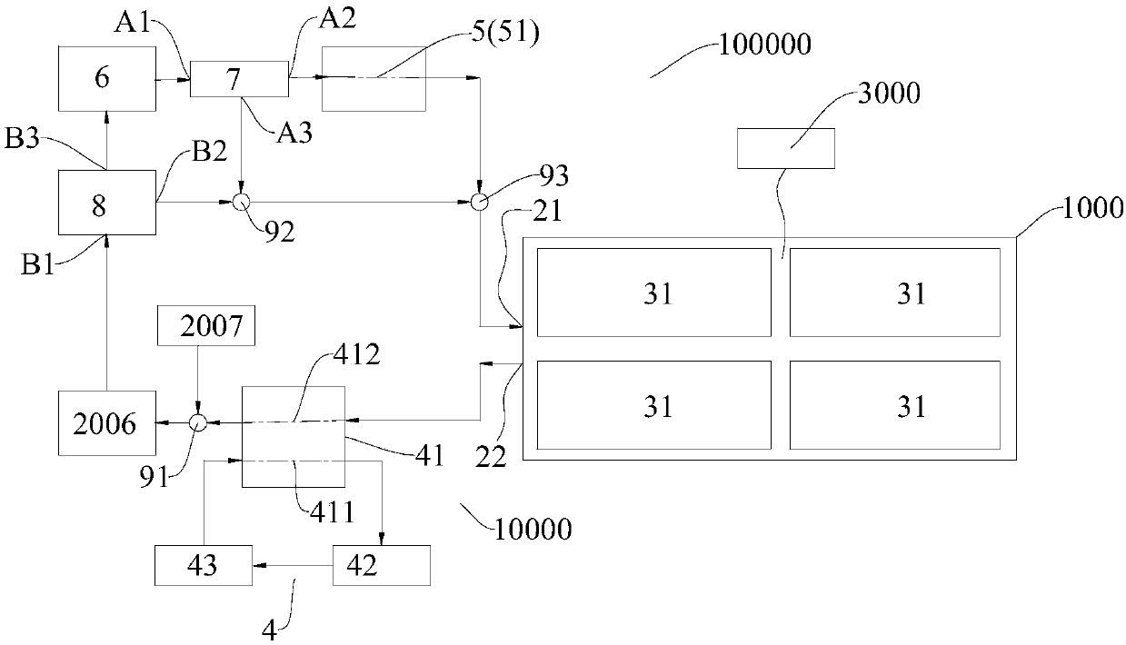
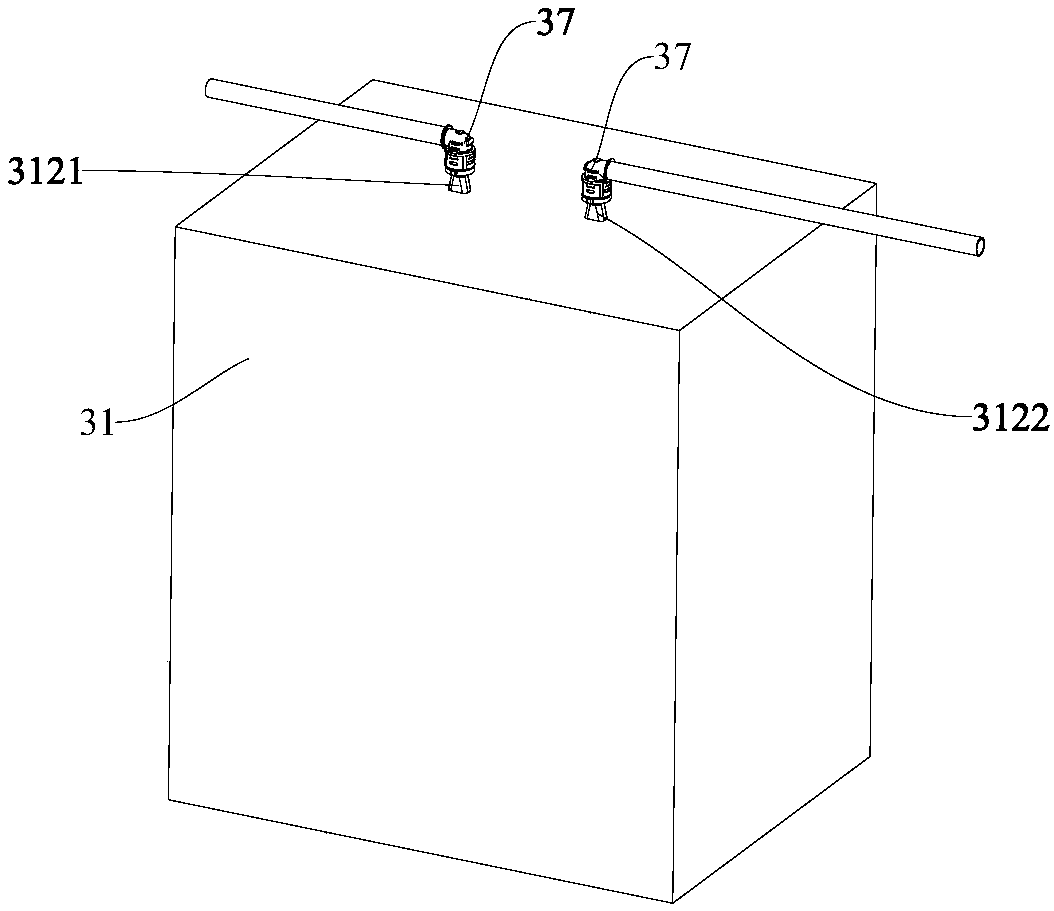
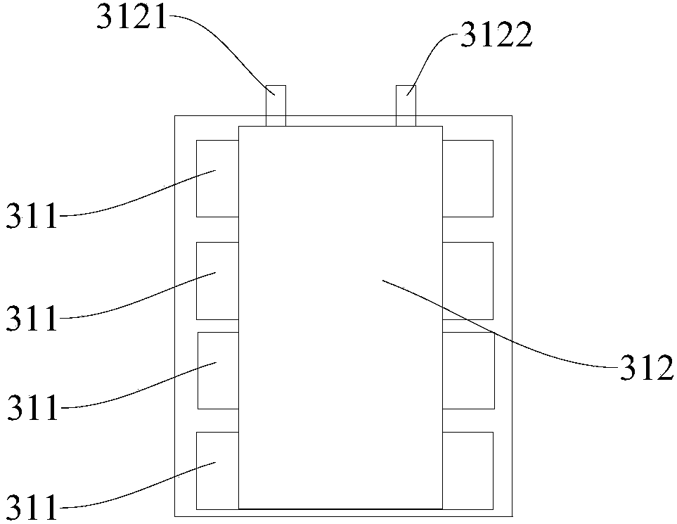
[0022] Refer below Figure 1-Figure 10 The thermal management system 10000 of the power battery pack according to the embodiment of the present invention will be described in detail. like Figure 1-Figure 10 As shown, the thermal management system 10000 of a power battery pack according to an embodiment of the present invention includes a power battery pack 1000 , a heat exchange circulation pipeline, an air conditioning system of an electric vehicle 100000 and a first PTC heater 6 .

[0023] The power battery pack 1000 can be installed on an electric vehicle to provide power output for the electric vehicle and an energy storage...


PUM


Abstract

The invention discloses a thermal management system of a power battery pack and an electric automobile with the system. The thermal management system comprises the power battery pack, a heat exchangecirculating pipeline, an air conditioning system of the electric automobile and a first PTC heater, wherein the power battery pack is provided with a main water inlet and a main water outlet; the twoends of the heat exchange circulating pipeline are connected with the main water inlet and the main water outlet respectively; the air conditioning system of the electric automobile comprises a refrigerating system and a warm air system, the refrigerating system comprises a compressor, a condenser and an evaporator, the evaporator comprises a first heat exchange channel and a second heat exchangechannel which are in heat exchange with each other, the first heat exchange channel is connected between the compressor and the condenser in series, and the second heat exchange channel is part of theheat exchange circulating pipeline; the warm air system comprises a warm air pipeline, and the warm air pipeline is selectively communicated with the heat exchange circulating channel; the first PTCheater is used for selectively heating heat exchange liquid in the heat exchange circulating channel. According to the thermal management system, heating and cooling of the power battery pack are uniform, the structure is simple, and the cost is low.

Description

technical field [0001] The invention relates to the technical field of power battery thermal management, in particular to a thermal management system for a power battery pack and an electric vehicle having the thermal management system. Background technique [0002] In the related art, the thermal management system of the power battery pack heats or cools the power battery pack by blowing cold or warm air from the air conditioning system of the vehicle into the air duct inside the power battery pack to exchange heat with the power battery pack. This kind of thermal management system, the heat of the power battery pack is uneven, the temperature difference between the multiple power battery modules in the power battery pack is large, and the airflow is used for heating or cooling, it is necessary to add a lot of fans and motors that drive the fans, increasing the electric power The power consumption of automobiles, and the high requirements for air duct design, the large occu...

Claims


Application Information

Patent Timeline
Patent Type & Authority Applications(China)
IPC IPC(8): B60L11/18B60H1/00
CPCB60H1/00278B60L58/26B60L58/27B60L2240/545Y02T10/70
Inventor 廖明龙
Owner BYD CO LTD
Why Eureka
Try Eureka