Solar tracking photovoltaic power generation device
What is AI technical title?
AI technical title is built by Patsnap AI team. It summarizes the technical point description of the patent document.
A photovoltaic power generation and sun tracking technology, applied in photovoltaic power generation, photovoltaic modules, solar thermal energy, etc., to achieve the effects of easy maintenance, simple structure, and increased absorption rate
Inactive Publication Date: 2018-03-27
王清
View PDF5 Cites 7 Cited by
Summary
Abstract
Description
Claims
Application Information
AI Technical Summary
This helps you quickly interpret patents by identifying the three key elements:
Problems solved by technology
Method used
Benefits of technology
Problems solved by technology
[0007] Aiming at the above problems, the present invention provides a solar tracking photovoltaic power generation device. By using the suction force of the electromagnet, the water tank is first driven to spray water on the photovoltaic panel, and then the cleaning roller is driven to rotate to clean the surface of the photovoltaic panel, so that the cleaning of the cleaning roller is similar to that of the photovoltaic panel. The effective combination of water spraying steps solves the technical problem of automatic cleaning of the surface of photovoltaic panels, realizes the rapid cleaning of the surface of photovoltaic panels, and recycles the cleaned water to improve the utilization rate of water resources
Method used
Image
Click on the blue label to locate the original text in one second.
Reading with bidirectional positioning of images and text.
Examples
Embodiment
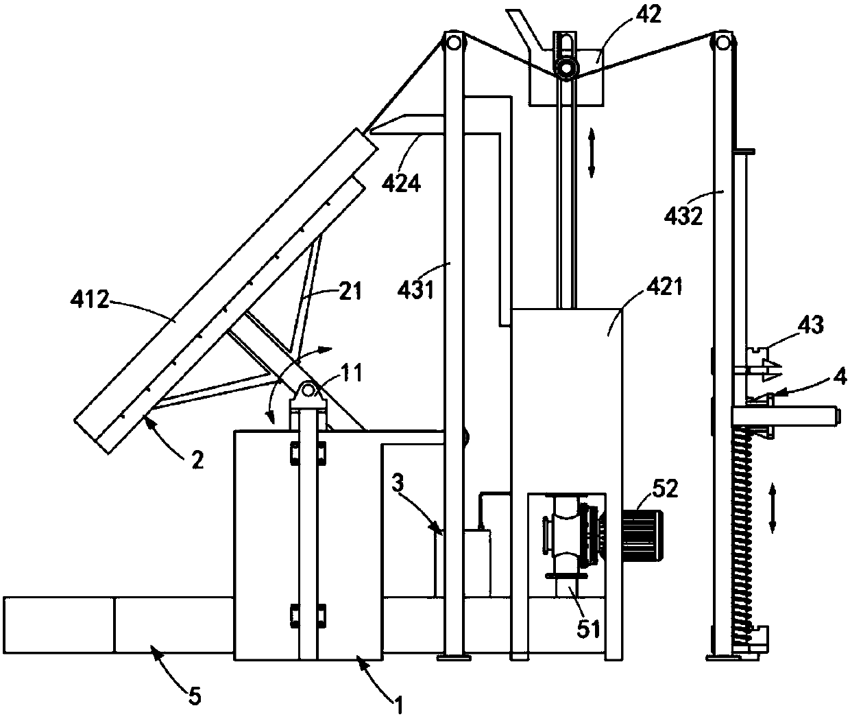
[0064] Such as figure 1 , figure 2 , image 3 and Figure 4 As shown, a solar tracking photovoltaic power generation device, including:
[0065] Mounting seat 1, the top center of the mounting seat 1 is symmetrically provided with a bearing seat 11;
[0066] A photovoltaic panel 2, the side of the photovoltaic panel 2 facing away from the sun is provided with a bracket 21, and the two ends of the bracket 21 are rotatably arranged on the bearing seat 11;
[0067] Tracking assembly 3, the tracking assembly 3 is arranged below the photovoltaic panel 2, it includes a liquid tank 31, the liquid tank 31 is connected to the end of the bracket 21 through a connecting rope 32, the connecting rope 32 and A first fixed pulley 321 is provided at the place where the mounting seat 1 is wound; and
[0068] The cleaning assembly 4, the cleaning assembly includes a cleaning unit 41, a water adding unit 42 and a driving unit 43, the cleaning unit 41 is arranged on the side facing the sun ...
Embodiment approach
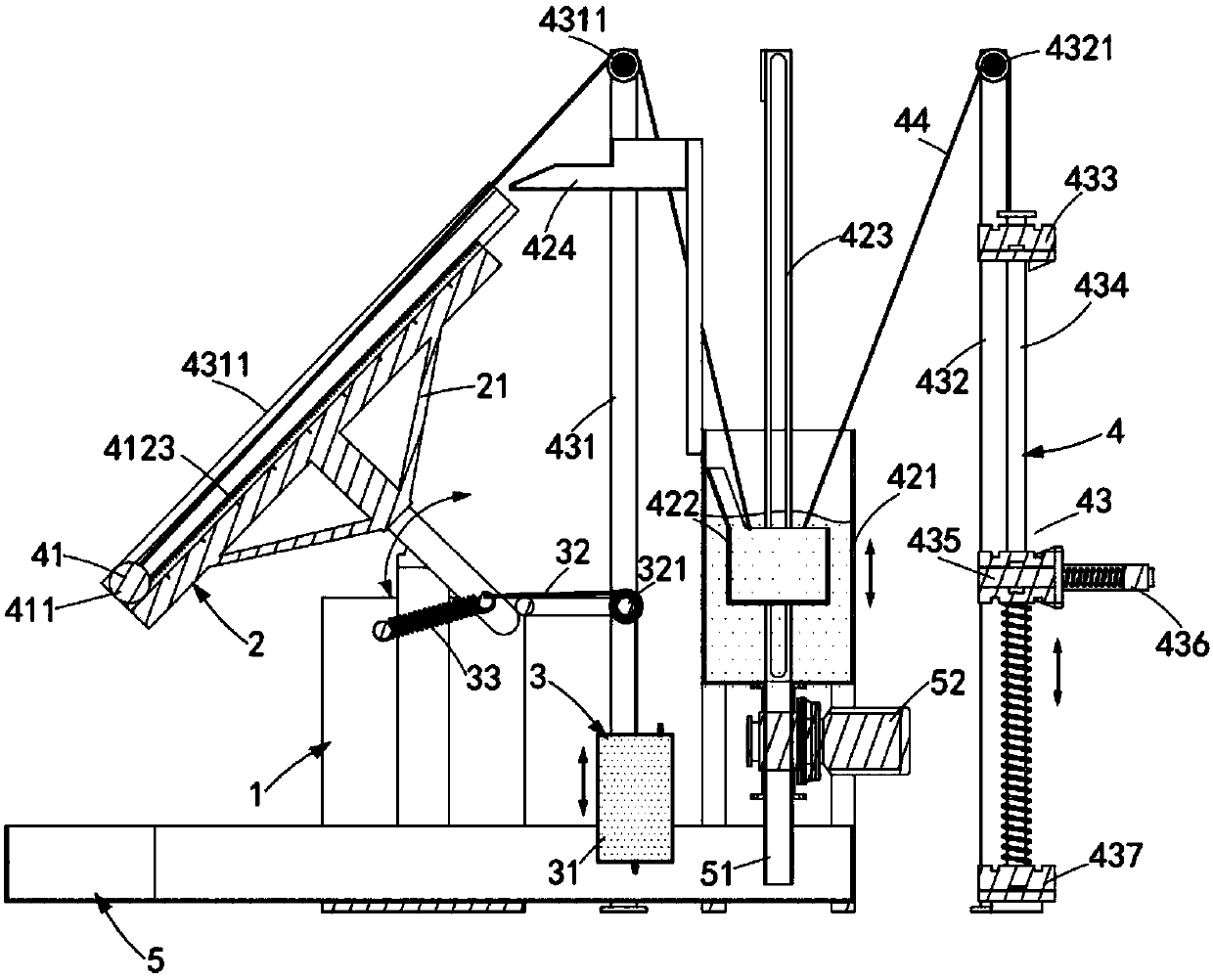
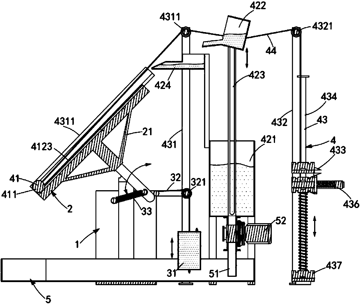
[0095] Such as figure 1 , figure 2 , Figure 10 and Figure 11 As shown, as a preferred implementation manner, the drive unit 43 includes:
[0096] The first pulley frame 431, the first pulley frame 431 is arranged between the photovoltaic panel 2 and the water tank 421, the second connecting rope 44 is wound on it, and it is connected with the second connecting rope 44 A second fixed pulley 4311 is provided at the winding part;
[0097] The second pulley frame 432, the second pulley frame 432 is arranged on the rear side of the water tank 421, the second connecting rope 44 is wound on it, and it is arranged with the winding position of the second connecting rope 44 There is a third fixed pulley 4321;
[0098] The first counterweight 433, the first counterweight 433 is connected with the second connecting rope 44, it is suspended directly below the second pulley frame 432, and it slides along the symmetrically arranged optical axis 434 ;
PUM
Abstract
The invention provides a solar tracking photovoltaic power generation device which is aimed at solving a technical problem of automatic cleaning of a photovoltaic panel surface. The solar tracking photovoltaic power generation device includes a mounting seat, a photovoltaic panel, a tracking assembly and a cleaning assembly. The cleaning assembly includes a cleaning unit, a water adding unit and adriving unit. The cleaning unit is installed on one sun-facing side of the photovoltaic panel. The water adding unit is installed on a back side of the photovoltaic panel. The driving unit is installed on a back side of the water adding unit, attracting force of an electromagnet is used in the driving unit to drive a water tank upward to spray water on the photovoltaic panel. A cleaning roller isdriven to clean the surface of the photovoltaic panel in a rotating manner, a cleaning step of the cleaning roller is effectively combined with a water spring step, the surface of the photovoltaic panel can be cleaned rapidly, and used water can be recovered and reused after the cleaning step to improve utilization rates of water resources.
Description
technical field [0001] The invention relates to the technical field of photovoltaic applications, in particular to a solar tracking photovoltaic power generation device. Background technique [0002] In today's world, the energy crisis and environmental pollution problems have attracted more and more attention. As a new type of renewable energy, solar energy is widely used due to its environmental friendliness. Photovoltaic power generation uses the photovoltaic effect of the semiconductor interface to generate A technology that directly converts light energy into electrical energy. It is mainly composed of three parts: solar panel components, controllers and inverters. The main components are composed of electronic components. The solar cells are packaged and protected after being connected in series to form a large-area solar cell module, and then cooperate with power controllers and other components to form a photovoltaic power generation device. [0003] After the pho...
Claims
Application Information
Patent Timeline
Application Date:The date an application was filed.
Publication Date:The date a patent or application was officially published.
First Publication Date:The earliest publication date of a patent with the same application number.
Issue Date:Publication date of the patent grant document.
PCT Entry Date:The Entry date of PCT National Phase.
Estimated Expiry Date:The statutory expiry date of a patent right according to the Patent Law, and it is the longest term of protection that the patent right can achieve without the termination of the patent right due to other reasons(Term extension factor has been taken into account ).
Invalid Date:Actual expiry date is based on effective date or publication date of legal transaction data of invalid patent.

